26.4 Connection
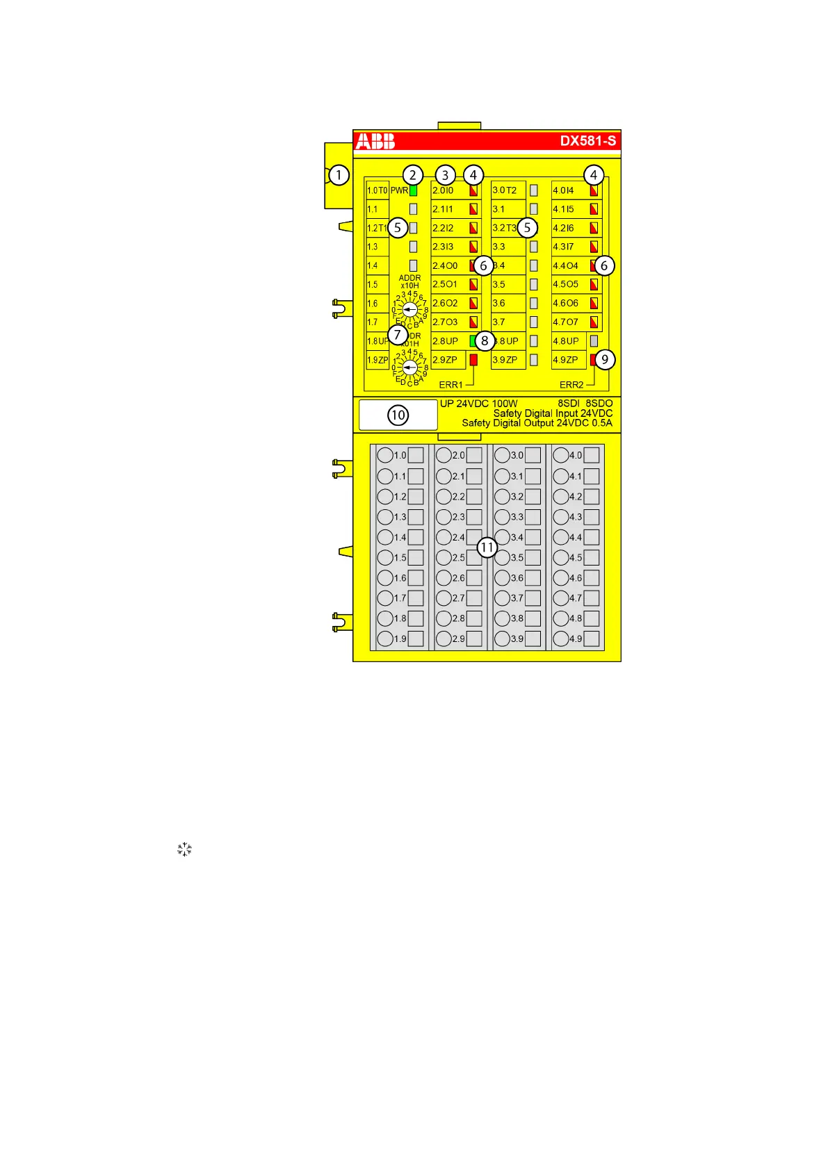
1 I/O bus
2 System LED
3 Allocation between terminal number and signal name
4 8 yellow/red LEDs to display the signal states of the digital inputs I0 to I7
5 4 Test pulse outputs T0 to T3
6 8 yellow/red LEDs to display the signal states of the digital outputs O0 to O7
7 2 rotary switches for setting the PROFIsafe address
8 1 green LED to display the state of the process supply voltage UP
9 2 red LEDs to display errors
10 Label
11 Terminal unit TU582-S(-XC)
Sign for XC version
2019/11/153ADR024117M02xx, 11, en_US206