52 CoriolisMaster FCB400, FCH400 CORIOLIS MASS FLOWMETER | OI/FCB400/FCH400-EN REV. E
… 7 Electrical connections
… Pin assignment
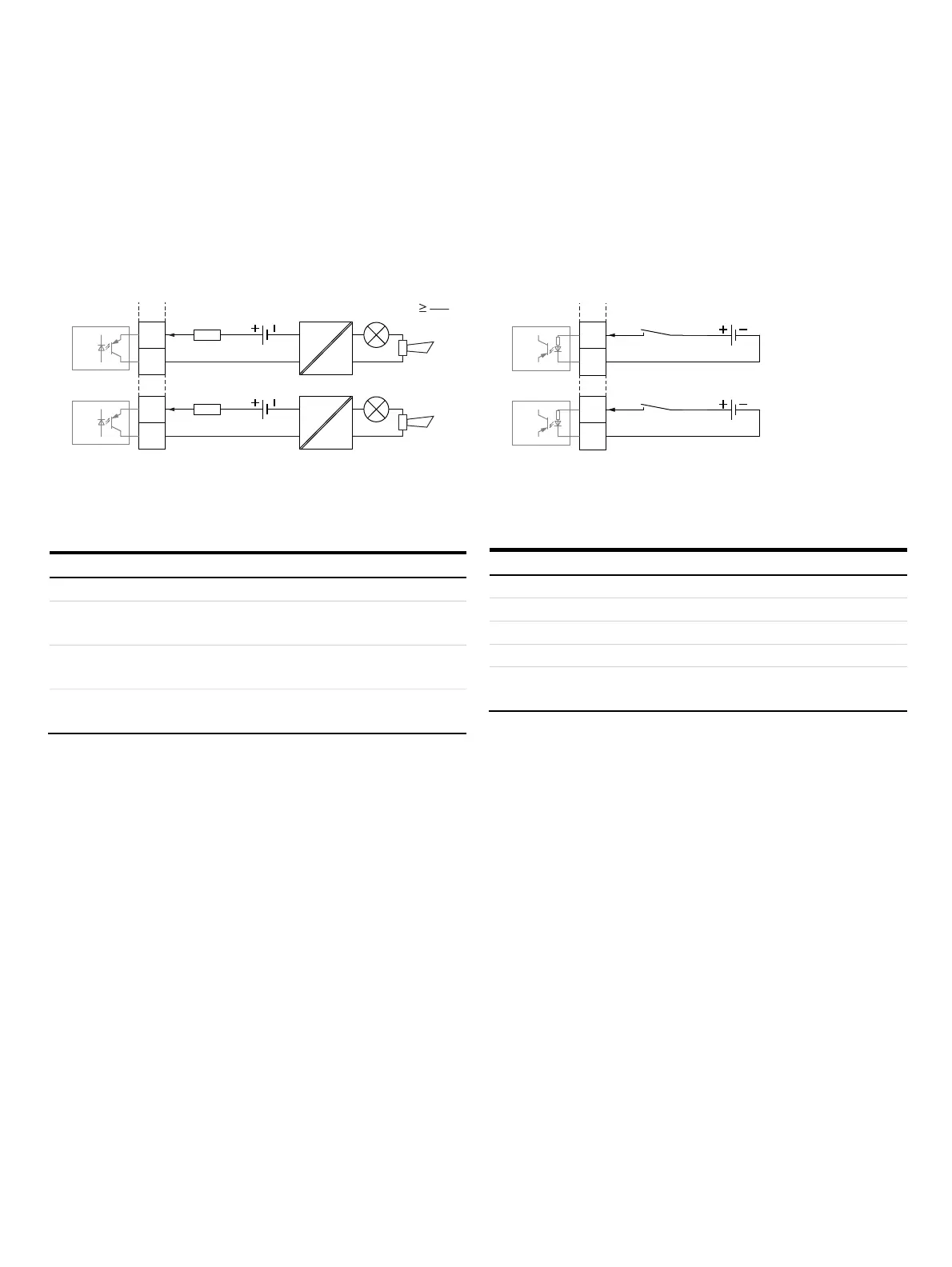
Digital output V1 / V2, V3 / V4 (plug-in module)
An additional binary output can be implemented via the ‘Passive
digital output (green)’ plug-in module.
Can be configured as an output for flow direction signaling,
alarm output etc. via on-site software.
G11898-01
R
B
U
CE
I
CE
16...30 V DC
V2-
V3+
IE
V1+
V4-
16...30 V DC
R
B
R
B
OC2
OC1
Figure 38: Plug-in card as binary output (I = internal, E = external, R
B
= load)
The plug-in module can be used in slot OC1 or OC2.
Binary output (passive)
Terminals V1 / V2, V3 / V4
Output ‘closed’ 0 V ≤ U
CEL
≤ 3 V
2 mA < I
CEL
< 30 mA
Output ‘open’ 16 V ≤ U
CEH
≤ 30 V DC
0 mA ≤ I
CEH
≤ 0.2 mA
Switching function Can be configured using software.
See Menu: Input / Output on page 107.
Digital output V1 / V2, V3 / V4 (plug-in module)
A digital input can be implemented via the ‘Passive digital input
(yellow)’ plug-in module.
Can be configured as an input for external counter reset,
external output deactivation etc. via on-site software.
G11598-01
16...30 V DC
V2-
V3+
IE
V1+
V4-
16...30 V DC
OC2
OC1
Ri
Ri
Figure 39: Plug-in card as digital input (I = internal, E = external)
The plug-in module can be used in slot OC1 or OC2.
Digital input
Terminals V1 / V2, V3 / V4
Input ‘On’ 16 V ≤ U
KL
≤ 30 V
Input ‘Off’ 0 V ≤ U
KL
≤ 3 V
Internal resistance R
i
6.5 kΩ
Function Can be configured using software.
See Menu: Input / Output on page 107.
 Loading...


