This document describes the Ekip CI - Contactor Interface for SACE XT2, XT4, XT5, XT7, and XT7M circuit breakers, providing installation and maintenance instructions.
Function Description
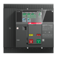
The Ekip CI (Contactor Interface) is a module designed to facilitate the connection and control of SACE Tmax XT series circuit breakers (XT2, XT4, XT5, XT7, XT7M) with external contactor systems or other control devices. It acts as an interface, allowing for remote operation and monitoring of the circuit breaker's status. The module integrates with the Ekip Supply and Ekip Com systems, enabling communication and power supply for its operation.
The Ekip CI module provides the necessary connections for external control signals, allowing the circuit breaker to be operated (e.g., tripped or reset) based on commands from a contactor or other control logic. It also provides feedback on the circuit breaker's status, such as whether it is open or closed, or if a trip has occurred. This interface is crucial for integrating the circuit breaker into larger electrical control systems, ensuring coordinated operation and enhanced safety.
For XT7M models, the interface includes specific features for managing the spring charging mechanism, indicating whether the spring is discharged or charged, and providing "Push ON" and "Push OFF" functionalities. The module also includes visual indicators (LEDs) to confirm its operational status and communication with the Ekip Supply and the release unit.
Important Technical Specifications
- Compatibility: SACE XT2, XT4, XT5, XT7, XT7M circuit breakers.
- Wiring: AWG 16-22 for control connections.
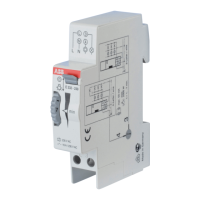
- Power Supply: Requires connection to an Ekip Supply module (110-240 VAC/DC).
- Communication: Integrates with Ekip Supply and Ekip Com modules via a local bus.
- Optional Modules: Supports optional Ekip Com modules for enhanced communication capabilities.
- Terminal Designations (XT2 - XT4 - XT5):
- K2, K1, W3, W4 for control signals.
- S751/2 optional cable connection.
- Terminal Designations (XT7 - XT7M):
- K2, K1, W3, W4 for control signals.
- S751/2 optional cable connection.
- Terminal Designations (XT5 F - P, XT5 W):
- W3, W4 for control signals.
- JR3, JS5 for specific connections.
- Terminal Designations (XT7 - XT7M):
- K61, K62, H61, H62, H63, H64 for various control and status signals.
- K51 CI, OCI, I PT100, I reset, SC3, SO3, R3, K for specific functions.
- LED Indicators: Visual feedback for power, communication, and operational status.
- Mounting: Designed for secure integration within the circuit breaker assembly.
Usage Features
- Remote Control: Enables remote "Push ON" and "Push OFF" operations for XT7M models, and general control for other XT series breakers.
- Status Monitoring: Provides visual and electrical feedback on the circuit breaker's status, including spring charge (for XT7M), open/closed position, and trip status.
- Easy Installation: Designed for straightforward installation with clear visual instructions for connecting the Ekip Supply and Ekip CI module.
- Modular Design: Allows for the integration of optional Ekip Com modules to expand communication and control capabilities.
- Diagnostic Indicators: LEDs on the Ekip CI module, Ekip Supply, and the release unit provide diagnostic information, helping to identify communication or power issues.
- Local Bus Activation: The installation procedure includes steps to activate the local bus via the circuit breaker's display interface (Display -> Settings -> Modules -> Local bus -> ON), ensuring proper communication.
- Cable Management: Instructions include proper routing and securing of cables (AWG 16-22) to ensure reliable connections.
- Click-in Mechanism: Features a "CLICK" mechanism for secure attachment of the Ekip CI module to the circuit breaker.
Maintenance Features
- Troubleshooting: The document provides guidance for troubleshooting, specifically mentioning that if the LEDs on the Ekip CI and Ekip Supply flash asynchronously with the release unit's LED, the circuit breaker manual should be consulted.
- Clear Wiring Diagrams: Detailed wiring diagrams are provided for different XT series models (XT2, XT4, XT5, XT7, XT7M) and optional modules (Ekip Com, S751/2), facilitating maintenance and fault finding.
- Component Identification: Key components and terminals are clearly labeled (e.g., K2, K1, W3, W4, H61, H62, OCI, I PT100), aiding in component replacement or inspection.
- Accessible Connections: The design allows for relatively easy access to wiring terminals for inspection, repair, or replacement of cables.
- Documentation Reference: The document frequently refers to additional documentation (e.g., "1SDH002009A1503," "1SDM000068R0001," "1SDM000005A10001," "1SDM000002A10001") for further details, ensuring comprehensive support for maintenance personnel.
- Optional Cable Usage: Specific instructions are provided for operations required only when using optional cables (e.g., S751/2), streamlining maintenance for different configurations.