Do you have a question about the ABB Zenith ZTG Series and is the answer not in the manual?
Inspect the transfer switch for damage incurred during transit and file a claim if necessary.
Store the transfer switch in its original package in a clean, dry location with uniform temperature.
Guidelines for safe electrical work practices and equipment handling to prevent hazards.
Explanation of hazard symbols (Danger, Warning, Caution, Notice) used throughout the document.
Glossary of terms and acronyms used in the manual for clarity.
Details on the warranty period, terms, and conditions for ZTG series transfer switches.
Information on quality assurance, serial number details, and applicable standards.
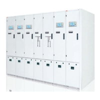
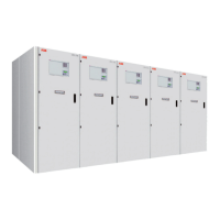
Description of the Zenith ZTG series automatic transfer switch and its components.
Comparison of delayed and open transition operation types and HMI differences.
Details on the Human Machine Interface (HMI) used for configuration and control.
Comparison of features for ZTG(D) controls, including voltage, frequency, and time delay settings.
Illustrates common scenarios for using automatic transfer switches between two power sources.
Describes the automatic switching sequences for different priority scenarios.
Explains features like automatic configuration, in-phase monitor, and powering supply scenarios.
Illustrates contact movement and position indication for open and delayed transitions.
Explains selection of operation modes (Manual, Locking, AUTO) via slide switch.
Procedure for operating the switch using the manual handle.
Steps to return the transfer switch to automatic mode using the HMI.
Description of LED indicators on the HMI for status, alarms, and modes.
Explanation of keypad functions for navigating the HMI and selecting parameters.
Guidance on navigating the menu tree to access settings and parameters.
Overview of the initial screens displayed on the HMI, including system status.
Procedure for accessing the main menu, entering passwords, and setting parameters.
Details on available menus and parameters for operation and system settings.
Information on using Ekip Connect software for communication, testing, and configuration.
Details on connecting via Bluetooth using the Ekip Bluetooth module.
Instructions for using the Ekip Programming module for software updates and parameter management.
Description and electrical characteristics of the OXEA1 auxiliary power supply module.
Details on the Ekip Signalling 2K-_ module for input/output signals.
Information on the Ekip Com Modbus RTU module for industrial network integration.
Details on the Ekip Com Profibus DP module for industrial network integration.
Information on the Ekip Com DeviceNet module for industrial network integration.
Details on the Ekip Com Modbus TCP module for Ethernet network communication.
Information on the Ekip Com Profinet module for Ethernet network communication.
Details on the Ekip Com EtherNet/IP module for Ethernet network communication.
List of alarms, their faults, and recommended actions for diagnosis and resolution.
List of warnings, their reasons, and necessary actions to address them.
List of information messages related to digital input/output functions.
Electrical specifications for automatic transfer switches, including voltage and frequency.
Schematic diagrams illustrating the wiring for open and delayed transition circuits.
Table of dimensions and weights for ZTG series enclosures, including UL Type 1.
Explanation of the design for long contact life and replacement of critical modules.
Recommended annual inspection tasks to ensure proper working order of the unit.
List of essential tools required for installation and maintenance tasks.
Procedures for inspecting equipment upon receipt and recommended storage conditions.
Guidelines for safe lifting and mounting of the automatic transfer switch panel.
Instructions for physically mounting the automatic transfer switch unit.
Specifications for mounting hole dimensions for ZTG series enclosures.
Procedure for mounting the operating handle in manual mode.
Specific steps for attaching the handle to the operating position in manual mode.
Procedure for mounting the HMI and transitioning to automatic mode.
Details on the physical installation of the HMI unit.
Guidelines for connecting power and control wires, including torque specifications.
Pre-energization checklist for verifying connections, settings, and component installation.
Step-by-step procedure for safely energizing the panel and performing initial configuration.
Information on using phase barriers to maintain clearance on transfer switch types.
Details on auxiliary contact blocks and their mounting.
Information on equipping ZTG(D) switches with auxiliary power supply and Ekip modules.
Description of the UL Type 3R HMI protective cover for water ingress protection.
List of replacement parts for ZTG series, including HMI module, manual handle, and mechanism.
| Poles | 2, 3, 4 |
|---|---|
| Short-Circuit Withstand Rating | Up to 200 kA |
| Enclosure | NEMA 1, 3R, 4, 4X, 12 |
| Amperage | 30-4000 A |
| Voltage | Up to 600 VAC |
| Operation | Automatic |
| Standards | UL 1008, CSA C22.2 No. 178 |
| Transfer Type | Open or Closed |