Do you have a question about the ABB Zenith ZTS T Series and is the answer not in the manual?
Inspect the transfer switch for transit damage upon receipt.
Guidelines for storing the transfer switch to prevent condensation and damage.
Details hazards and precautions related to electrical safety during operation.
Information on installing the transfer switch and accessories.
Guidance on operating and maintaining the transfer switch.
Explains hazard symbols (Danger, Warning, Caution, Notice) used in the manual.
Provides definitions for key terms and acronyms used in the document.
Outlines the warranty period and terms for the transfer switch products.
Details quality assurance, serial number information, and applicable standards.
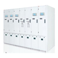
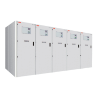
Provides a general description of the Zenith ZTS T-series ATS and its components.
Differentiates between open, delayed, and closed transition operation types.
Describes the Human Machine Interface (HMI) for controlling and configuring the ATS.
Compares features of ZTS(D/CT) controls, including voltage, frequency, and time delay settings.
Illustrates common use cases for the automatic transfer switches in emergency systems.
Details the switching sequences for automatic transfer under different priority scenarios.
Explains features like automatic configuration, in-phase monitor, and powering scenarios.
Explains how to interpret position indicators for R5 and 63L models.
Provides step-by-step instructions for manual operation of R5 and 63L ATS models.
Describes the initial screen and navigation options of the HMI.
Guides users on navigating menus and adjusting system parameters.
Lists and explains various operational modes and parameters available in the HMI.
Explains how to view voltage, current, power, and other measurements on the HMI.
Details the Ekip Connect software for communication and testing of ATS.
Explains the use of the Ekip Programming module for software updates and parameter settings.
Describes the OXEA1 auxiliary power supply module and its electrical characteristics.
Covers the Ekip Signalling 2K-_ module for input/output signals and status LEDs.
Introduces various Ekip Com modules (Modbus RTU, Profibus DP, DeviceNet, etc.).
Lists common alarm messages, their faults, and recommended actions.
Details warning messages, their reasons, and troubleshooting steps.
Lists informational messages related to system status and activated functions.
Provides electrical ratings, frequency, and voltage measurement accuracies.
Illustrates single-phase and three-phase circuit diagrams for ATS.
Shows dimensions and weights of ZTS series ATS in UL Type 1 Enclosure.
Explains the design philosophy regarding maintenance needs and component replacement.
Recommends an annual inspection checklist for ensuring proper operation.
Lists essential tools required for installation and maintenance tasks.
Provides guidelines for inspecting equipment upon receipt and for proper storage.
Details safe lifting and mounting procedures for the ATS panel.
Presents mounting hole dimensions for various ATS models.
Specifies wire connection types, ranges, and torque requirements.
Outlines final checks before energizing the transfer switch.
Provides steps for safely energizing the ATS panel and performing initial configuration.
Describes auxiliary power supply and Ekip modules that can be equipped with ATS.
Details the HMI protective cover for enhanced safety and protection.
| Manufacturer | ABB |
|---|---|
| Poles | 2, 3, 4 |
| Bypass Isolation | Optional |
| Series | ZTS T Series |
| Amperage | 30-4000 A |
| Voltage | Up to 600 VAC |
| Standards | UL 1008, CSA C22.2 No. 178 |
| Operation | Automatic |
| Enclosure | NEMA 1, 3R, 12 |