L6555
Emax
22/74
Doc. no.
Model
Apparatus
Scale
Page No
1SDH000460R0002
8.3.6. Electrical and mechanical accessories
- Check that the accessories are fi xed to the switch
- Check that the electrical accessories are connected to the switch
- Reduction gear: after 10000 operations check brushes for wear and replace the reduction gear if necessary.
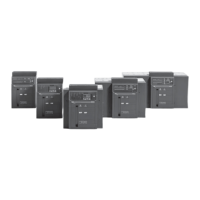
- Check that the releases (SOR-UVR-SRC) are in good condition (no excessive wear, overheating, breakages) Fig. 36.
- Check that the mechanical operation counter is operating correctly (if applicable) by running an operation on the switch.
Fig. 36
8.3.7. Protection releases
- Supply the protection release from a PR030/B battery unit.
- Check that the protection release is working correctly: run “Trip Test” (PR121, PR122, PR123) and “Autotest” (PR122, PR123)
for release.
- Use release PR122 or PR123 to check that there are no alarms on the display and via front LEDs.
- Use release PR121 to check that there are no alarms via front LEDs.
- Check that the cables are correctly connected to the release modules and to the release (if applicable).
- On PR122 and PR123 check the wear percentage to the switch contacts.
- At the end, remove the battery unit PR030/B from the relay.
Consult this manual for details about release PR121.
Consult manual 1SDH000460R0102 for details about releases PR122-PR123.
8.3.8. Test with SD Testbus2 (optional)
- Connect unit BT030 or BT030-USB to the relay to be tested.
- Run the programme SD.TestBus2 on a PC with a Bluetooth or USB connection, depending on the version of BT030 used.
- Once the connection between the relay and PC has been installed, check that there are no alarm signals from the relay; other-
wise, consult the paragraphs ‘Error Messages’ and/or ‘Troubleshooting’ in this manual.
- In normal operating conditions the trip test and the autotest can be run (depending on the type of relay); for future checks, we
advise inserting the current date in the User Data and/or Tag Name area. These data will be stored inside the relay.
- Remove the BT030 or BT030-USB from the relay.
Consult this manual for details about release PR121.
Consult manual 1SDH000460R0102 for details about releases PR122-PR123.
8.3.9. Maintenance operations; fi nal checks
- Refi t all parts and if necessary reconnect the auxiliary supply.
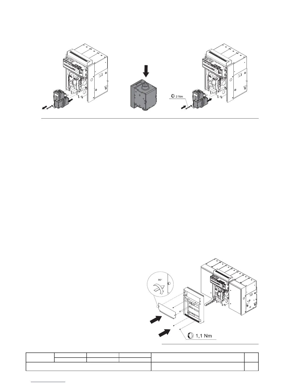
- Refi t the cap as indicated in fi gure 37.
- Return the movable part to the TEST-ISOLATED position.
- Use the different auxiliaries in turn to run the following 10
operations:
- Opening (both local and remote as applicable)
- Closing (both local and remote as applicable)
- Release by trip test from the relay
- Check the operations according to this sequence:
- Open - Springs unloaded
- Open - Springs loaded
- Closed - Springs unloaded
- Closed - Springs loaded
- Check operation of the accessories, if present
- Check operation of reduction gear (if present)
- Check operation of minimum voltage release (if present)
- Check operation of opening release (if present)
- Check operation of closing release (if present)
- Check operation of auxiliary contacts of switch (if present)
- Check operation of lock of switch in open position
(with key or padlocks) (if present)
Fi