L6555
Emax
42/74
Doc. no.
Model
Apparatus
Scale
Page No
1SDH000460R0002
12.4.6. Protection against instantaneous short-circuit “Iinst”
The purpose of this protection is to maintain the integrity of the circuit-breaker and installation in the case of particularly high
current requiring shorter reaction times than those guaranteed by the instantaneous short-circuit protection.
The protection cannot be disabled. It has a single fi xed time protection curve and the threshold level is exclusively at the charge
of ABB personnel.
12.4.7. Summary table of protections
Protection
Disabling
Trip threshold Trip time
Trip
threshold
tolerance
(2)
Trip
time
tolerance
(2)
L
(t=k/I
2
)
I1
=
0.4 - 0.425 - 0.45 - 0.475 - 0.5 -
0.525 - 0.55 - 0.575 - 0.6 - 0.625 -
0.65 - 0.675 - 0,7 - 0.725 - 0.75 -
0.775 - 0.8 - 0.825 - 0.85 - 0.875 -
0.9 - 0.925 - 0.975 - 1 x In
t1
=
3 - 12 - 24 - 36 -
48 - 72 - 108 -
144 s
(1)
@I
f
=3I1
Release
between
1.05 and 1.2
x I1
± 10% I
f
6 x In
± 20% I
f
> 6 x In
S
(t=k)
I2
=
1 - 1.5 - 2 - 2.5 - 3 - 3.5 - 4 - 5 -
6 - 7 - 8 - 8.5 - 9 - 9.5 - 10 x In
Where I
f
> I2 ± 7% I
f
6
x In
± 10% I
f
>6
x In
The best of the two data:
± 10% o ± 40 ms
t2
=
0.1 - 0.2 - 0.3 - 0.4 -
0.5 - 0.6 - 0.7 - 0.8 s
S
(t=k/I
2
)
I2
=
1 - 1.5 - 2 - 2.5 - 3 - 3.5 - 4 - 5 -
6 - 7 - 8 - 8.5 - 9 - 9.5 - 10 x In
t2
=
0.1 - 0.2 - 0.3 - 0.4 -
0.5 - 0.6 - 0.7 - 0.8 s
@ 10 In
± 7% I
f
6
x In
± 10% I
f
>6
x In
± 15% I
f
6 x In
± 20% I
f
> 6 x In
I
(t=k)
I3
=
1,5 - 2 - 3 - 4 - 5 - 6 - 7 - 8 - 9 -
10 - 11 - 12 - 13 - 14 - 15 x In
30 ms
± 10%
G
(t=k)
I4
=
0,2 - 0,3 - 0,4 - 0,6 - 0,8 - 0,9 -
1 x In
Where I
f
> I4
± 7%
The best of the two data:
± 10% o ± 40 ms
t4
=
0.1 - 0.2 - 0.4 - 0.8 s
G
(t=k/I
2
)
I4
=
0,2 - 0,3 - 0,4 - 0,6 - 0,8 - 0,9 -
1 x In
Minimum trip time
± 7% ± 15%
t4
=
0.1 - 0.2 - 0.4 - 0.8 s
(1) The minimum value of this trip is 1s regardless of the type of curve set
(self-protection).
(2) These tolerances apply in the following conditions:
- Self-powered relay (no start-up) with 2 or 3 supplied phases
and/or in presence of auxiliary supply. .
- operating temperature within the -25° ...70° range
- primary current values within the operating limits (see par.
12.2.5.1)
For all cases not covered by the above hypotheses, the following tolerances apply:
Protection rip threshold Trip time
L
Release between 1,05 e 1,25 x I1 ± 20%
S
± 10% ± 20%
I
± 15% 60ms
G
± 10% ± 20%
Others
± 20%
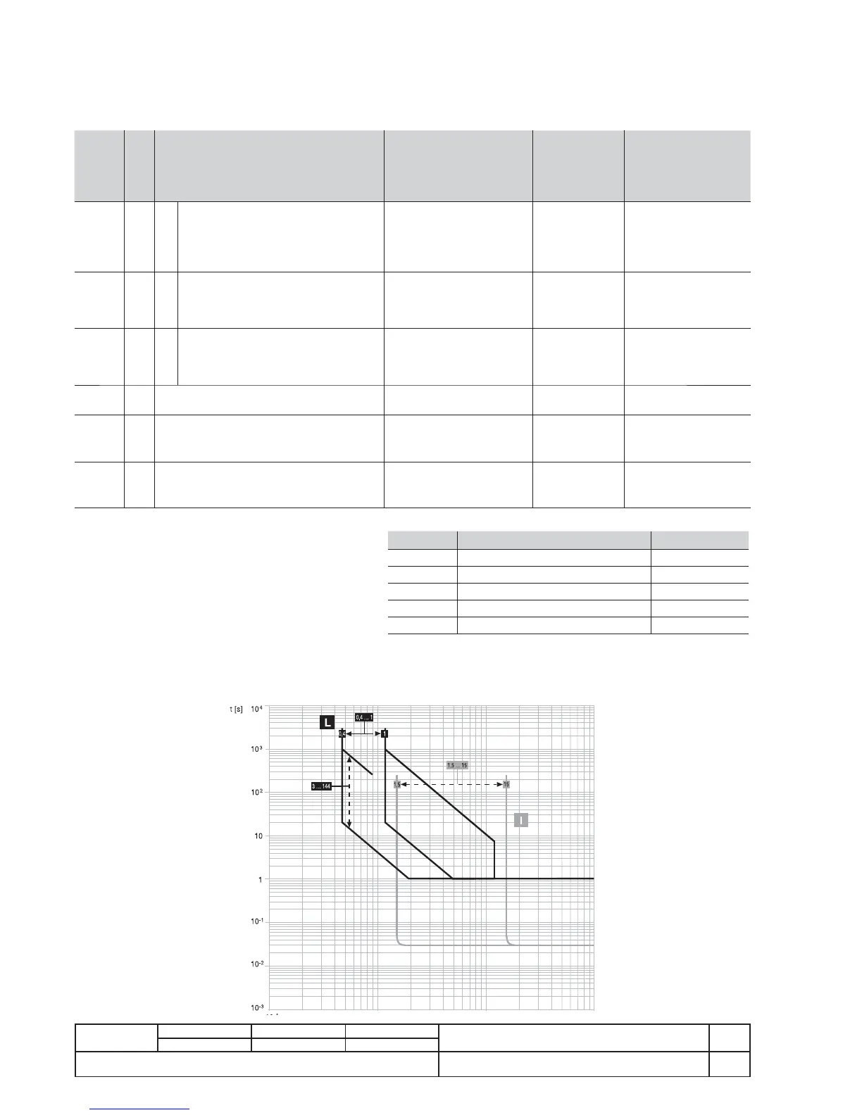
12.4.8. Trip curves
The trip curves provided are merely for guidance and only show a sub-group of the possible selections.
12.4.8.1. Trip curves for functions L-I