L6555
Emax
8/74
Doc. no.
Model
Apparatus
Scale
Page No
1SDH000460R0002
4.3.2. Installation of the fi xed part (Fig. 12)
Attach the fi xed part by means of the screws (1), washers (2) and nuts (3) (M8 x 16), supplied by ABB SACE. if other screws are
used, make sure that the head of the screws does not extend more than 5.5 mm from the base of the fi xed part.
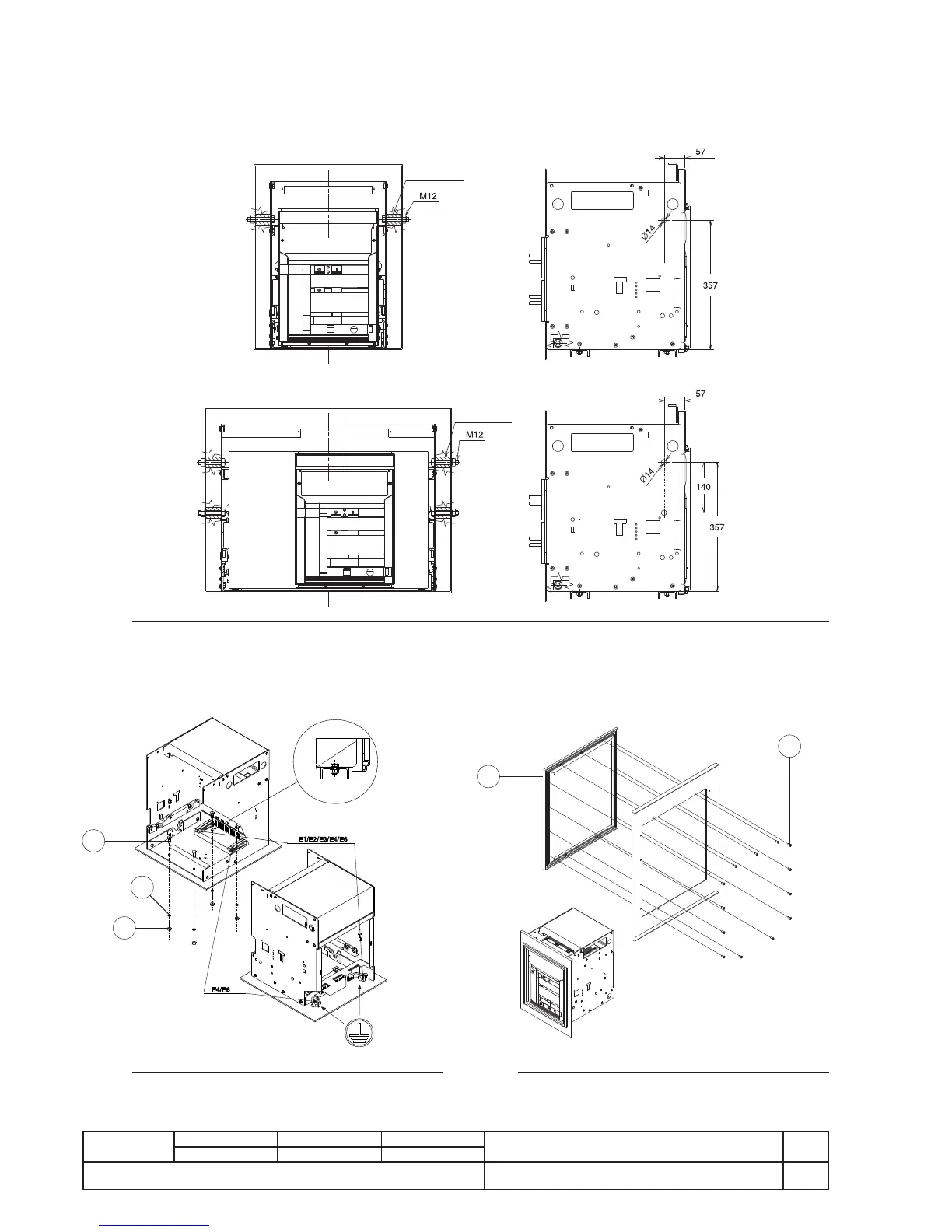
4.3.3. Installation of the fi xed part on board a ship (Fig. 11)
Regarding the fi xing points of the SACE Emax withdrawable version air circuit-breakers, for applications on board a ship, addi-
tional fi xing on the sides of the fi xed part itself is recommended (the M12 screws and the spacers are not provided in the supply).
Fig. 11
E1 - E2 - E3
E4 - E6
Spacers
Spacers
4.4. Installation of the fl ange on the compartment door
(Fig. 13)
- Make the compartment door drillings specifi ed in the “Overall dimensions” paragraph.
- Attach the fl ange (1) on the front of the compartment door, fi xing it from the inside by means of the self-tapping screws (2).
1
2
1
2
3
Fig. 12
Note
(*) For the E1-E2-E3 fi xed parts,
there are four fixing points,
whereas there are six for E4-E6.
Fig. 13