23/36
6.3. Weights and Dimensions
The weight specifications refer to the apparatus / accessories and do not include any specifications for
packaging.
Designation Weight [kg] Outside Dimensions W*D*H [mm]
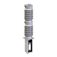
Apparatus FSK 1025
120 (1) .-… 150 (2) 320 x 320 x 1900
Small Control box
25 400 x 320 x 440
Large Control box
50 550 x 330 x 800
Table 15 Approx. values (
(1)
for silicon insulators /
(2)
for ceramic insulators /
(3)
without mounting
profiles)
6.4. Operating Conditions
Designation Value
Operating environment temperature -40°C.. +50°C
Altitude < 1000m
Pressure 600 … 1100mbar abs.
Table 16 Standard operation conditions
6.5. Torques for tightening screws and nuts
Torques described in the table below are to be applied with a suitable torque spanner.
For the screw sizes M6 to M16, the tightening torque corresponds to screws with a strength quality of 8.8 and an
achieved permissible tensioning of 90% of the yield point Rp0.2.
Thread Size Nominal Tightening Torque [Nm]
M4 3
M5 5.9
M6 10.1
M8 24.6
M10 48
M12 84
M16 206
Table 17 Screw tightening torques (screws are lubricated)
6.6. Interfaces
6.6.1. Mechanical/Electrical
The general definition of the interfaces can be taken from the associated, applicable dimensional drawing and
can vary from project to project. This applies to the fastening holes and screws of the pole, the control box and to
the layout of the main and auxiliary power connections.
6.6.2. Earthing Connections
The exact earthing positions of the apparatus can be taken from the associated, applicable dimensional drawing.
The earthing connection is to be carried out with the M12 screws/ stud.
 Loading...