EasyManua.ls Logo

ABB HD4/R User Manual

ABB HD4/R
38 pages
To Next Page IconTo Next Page
Page #1 background imageLoading...
Page #1 background image
Power and productivity
for a better world
TM
Medium voltage products
HD4/R
-
HD4/S
-
HD4/UniAir
-
HD4/UniMix
-
HD4/R-SEC
Installation and operating instructions
I. Introduction 4
1. Packing and transport 5
2. Inspection on arrival 6
3. Storage 7
4. Handling 8
5. Description 9
5.1 General information 9
5.2 Basic configuration 9
5.3 Operating mechanism 10
5.4 Fixed circuit-breakers 10
5.5 Plug-in circuit-breakers 11
5.6 Gas pressure monitoring device (on request) 11
5.7 Circuit-breaker specifications 12
6. Instructions for circuit-breaker operation 17
6.1 Safety indications 17
6.2 Operating and signalling parts 17
6.3 Instructions for circuit-breaker operation 17
7. Installation 19
7.1 General information 19
7.2 Normal installation conditions 19
7.3 Preliminary operations 19
7.4 Installation of fixed circuit-breakers 19
7.5 Installation of plug-in circuit-breakers 19
7.6 Power circuit connections 19
7.7 Earthing 20
7.8 Connection of the auxiliary circuits 20
7.9 Overall dimensions 21
8. Putting into service 31
8.1 General procedures 31
9. Routine inspections 32
9.1 General information 32
9.2 Inspection schedule 32
9.3 Troubleshooting 32
10. Servicing operations 33
11. Instructions for handling apparatus containing
SF
6
gas 34
12. Spare parts and accessories 35
12.1 List of spare parts 35
13. Quality of the products and environmental
protection 36

Other manuals for ABB HD4/R

Question and Answer IconNeed help?

Do you have a question about the ABB HD4/R and is the answer not in the manual?

ABB HD4/R Specifications

General IconGeneral
Rated Voltage12 kV
Rated Frequency50/60 Hz
Mechanical Life10, 000 operations
Operating MechanismSpring-operated
StandardsIEC 62271-100
Insulation MediumSF6
Rated Short-Circuit Breaking Current25 kA

Summary

1. Introduction

1. Packing and transport

2. Inspection on arrival

3. Storage

4. Handling

5. Description

5.1 General information

Details the construction and versions of the circuit-breakers, including standards.

5.2 Basic configuration

Lists the standard components included in the basic circuit-breaker configuration.

5.3 Operating mechanism

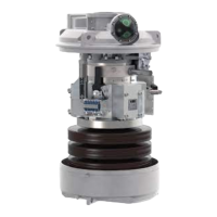
Explains the ESH operating mechanism, spring loading, and remote operation capabilities.

5.4 Fixed circuit-breakers

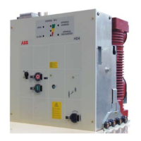
Describes the fixed version, its supports, terminal box, and earthing screw.

5.5 Plug-in circuit-breakers

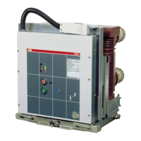
Details plug-in types for UniSwitch/UniAir, their characteristics, and racking positions.

5.6 Gas pressure monitoring device (on request)

Explains the SF6 gas pressure monitoring device and its available configurations.

5.7 Circuit-breaker specifications

5.7.1 General specifications of fixed circuit-breakers with rh lateral operating mechanisms (12 - 17.5 - 24 - 36 kV)

Provides detailed technical specifications for fixed HD4/R circuit-breakers across various voltage ratings.

5.7.2 General specifications of fixed circuit-breakers with rh lateral operating mechanisms for ABB UniSwitch switchgear (12 - 17.5 - 24 kV)

Presents technical specifications for fixed HD4/S circuit-breakers used in UniSwitch switchgear.

5.7.3 General specifications of fixed circuit-breakers with rh lateral operating mechanisms for ABB UniMix switchgear (12 - 17.5 - 24 kV)

Details technical specifications for fixed HD4/UniMix circuit-breakers used in UniMix switchgear.

5.7.4 General specifications of fixed circuit-breakers with rh lateral operating mechanisms for ABB UniAir switchgear (12 - 17.5 - 24 kV)

Provides technical specifications for fixed HD4/UniAir circuit-breakers used in UniAir switchgear.

5.7.5 General specifications of fixed circuit-breakers with rh lateral operating mechanisms for ABB UniSec switchgear (12 - 17.5 - 24 kV)

Lists technical specifications for fixed HD4/R-SEC circuit-breakers used in UniSec switchgear.

6. Instructions for operating the circuit-breaker

6.1 Safety indications

Provides critical safety warnings regarding installation, handling, and operations outside the switchgear.

6.2 Operating and signalling components

Identifies and labels the key operating and signalling components on the circuit-breaker.

6.3 Instructions for circuit-breaker operation

Details manual and electrical operation procedures, including spring loading.

6.3.4 Closing operation

Explains how to perform the closing operation using the closing pushbutton, including remote control.

6.3.5 Opening operation

Details how to perform the opening operation using the opening pushbutton and remote control.

7. Installation

7.1 General information

Emphasizes the importance of correct installation and the need for qualified personnel.

7.2 Normal installation conditions

Specifies the environmental conditions required for proper installation and operation.

7.3 Preliminary operations

Outlines initial steps before installation, such as cleaning and checking terminals.

7.4 Installation of fixed circuit-breakers

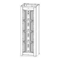
Provides instructions for mounting and fixing the circuit-breaker in place.

7.5 Installation of plug-in circuit-breakers

Describes the installation process for plug-in circuit-breakers within switchgear.

7.6 Power circuit connections

Covers general recommendations, dimensions, surface treatment, and assembly of power connections.

7.6.1 General recommendations

Provides guidance on ensuring clean, properly sized, and supported power connections.

7.6.2 Maximum dimensions of the connections

Specifies dimensional requirements for connections on fixed HD4/R circuit-breakers.

7.6.3 Surface treatment of the connections

Recommends surface treatment for connection contacts, preferably silver-plating.

7.6.4 Assembly of the connections

Details procedures for preparing and assembling electrical connections to the terminals.

7.7 Earthing

Explains the process for earthing fixed version circuit-breakers using the designated screw.

7.8 Connection of the auxiliary circuits

Describes how to connect auxiliary circuits for both fixed and plug-in breakers.

7.9 Overall dimensions

7.9.1 Fixed HD4/R, 12 ... 24 kV, 630 ... 1250 A

Shows detailed dimensions for fixed HD4/R circuit-breakers at 12-24 kV, 630-1250 A.

7.9.2 Fixed HD4/R, 12 ... 24 kV, 630 ... 1250 A

Displays dimensions for fixed HD4/R circuit-breakers, likely a different configuration or view.

7.9.3 Fixed HD4/R, 36 kV, 630 ... 1250 A

Presents dimensional drawings for fixed HD4/R circuit-breakers at 36 kV.

7.9.4 Plug-in HD4/S, 12 ...24 kV, 630 ... 1250 A

Provides dimensional drawings for plug-in HD4/S circuit-breakers.

7.9.5 HD4/Uniair, 12 ... 24 kV, 630 ... 1250 A

Shows dimensional drawings for HD4/Uniair circuit-breakers.

7.9.6 HD4/Uniair-F, 12 ... 24 kV, 630 A

Details dimensions for HD4/Uniair-F circuit-breakers.

7.9.7 HD4/Uniair-2R, 12 ... 24 kV, 630 ... 1250 A

Presents dimensional drawings for HD4/Uniair-2R circuit-breakers.

7.9.8 HD4/Uniair-A, 12 ... 24 kV, 630 ... 1250 A

Provides dimensional drawings for HD4/Uniair-A circuit-breakers.

7.9.9 HD4/UniMix-F, 12 ... 24 kV, 630 ... 1250 A

Shows dimensional drawings for HD4/UniMix-F circuit-breakers.

7.9.10 HD4/R-SEC, 12 ... 24 kV, 630 ... 800 A

Displays dimensional drawings for HD4/R-SEC circuit-breakers.

8. Putting into service

8.1 General procedures

Outlines essential procedures and checks before putting the circuit-breaker into service.

9. Routine inspections

9.1 General information

Explains the maintenance-free nature and factors influencing inspection frequency.

9.2 Inspection schedule

Provides a schedule of inspections, frequency, and criteria for routine checks.

9.3 Troubleshooting

Lists common faults, their possible causes, and suggested inspections/remedies.

10. Servicing operations

11. Instructions for handling apparatus containing SF6 gas

12. Spare parts and accessories

12.1 List of spare parts/Accessories

Lists various spare parts and accessories available for the circuit-breaker.

13. Quality of the products and environmental protection

Related product manuals