Operation Manual / 4 Product description / A150-M.. - A155-M..
Page 88 /
© Copyright 2017 ABB. All rights reserved.
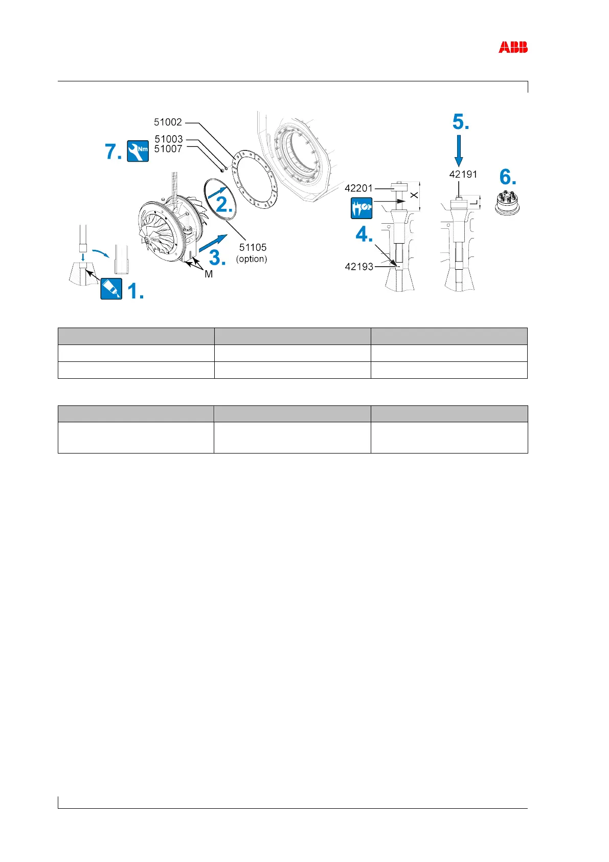
Figure 44: Installing the cartridge group 2
A155 144 ±2 mm 72 ±2 mm
Table 40: Fitting the turbocharger, dimensions X,L
51007 M16
175 Nm
M16
175 Nm
Table 41: Tightening torque (51007)
1. Lightly lubricate the hole in the bracket, into which the centering bush (42193) is inserted,
with screw grease.
2. If present: Insert the metal C-ring (51105).
3. Move the cartridge group into the turbine casing and align with the markings (M) made on
the bracket at the time of disassembly.
4. Rotate the clamping nut (42201) upwards up to the end of the threaded rod and insert the
centering bush (42193) into the hole.
Check dimension X (if dimension X is not reached, the turbocharger must be realigned).
5. Screw in the threaded rod until value L is reached.
6. Tighten the pressure screws of the clamping nut. (see Tightening pressure screws [➙ 19])
7. Secure fastening strips (51002) together with nuts (51007) and Verbus Ripp® washers
(51003).