Operation Manual / TPS48-D/E.. - TPS61-D/E..
7 Removal and installation / 7.4 Installing the turbocharger
© Copyright 2020 . All rights reserved. HZTL2410_EN Rev.F March 2020
u Loosen the fixing screws (D) on the bearing casing.
u Lift the turbocharger from the engine and put it down.
u Cover oil connections.
7.4 Installing the turbocharger
u Remove covers from oil connections.
u Visually inspect O-ring gaskets of oil supply and drain pipe (O-ring
gaskets for engine are not included in the scope of delivery of ABB).
**) When the turbocharger is mounted on the engine support, the bolt
threads and screw heads must be lightly oiled (assumed friction coeffi-
cient µ = 0.12 for tightening torque)
Product Through hole in
bearing casing
[mm]
Thread size
[mm]
Tightening
torque
[Nm]
Strength class
in acc. with
DIN/ISO 898
TPS48 17 M16 230 10.9/12.9
TPS52 21 M20 455 10.9/12.9
TPS57 21 M20 455 10.9/12.9
TPS61 25 M24 780 10.9/12.9
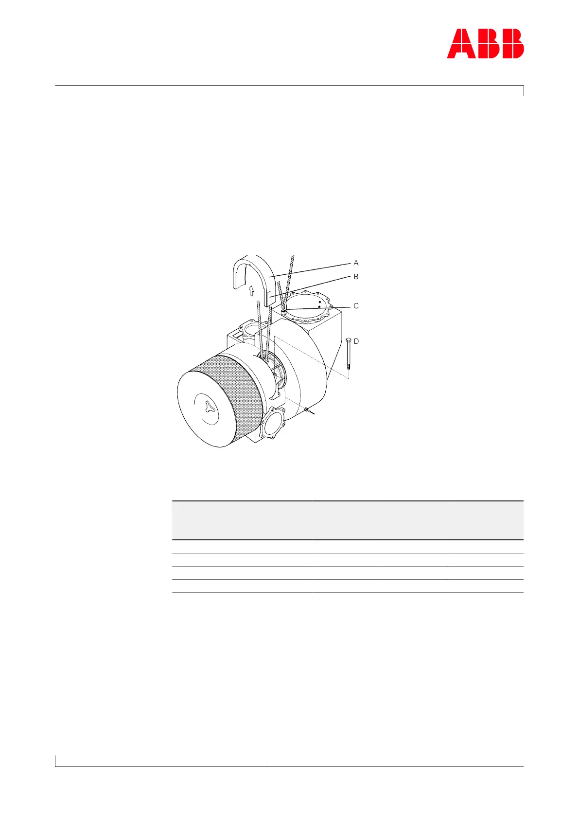
u Attach lifting gear to bearing casing.
u If a gas outlet manifold is provided, sling lifting gear around it addi-
tionally or fasten it to lifting gear using a swivel lifting eye(C) (see
also section Transport / Weights).
u Lift turbocharger, place on bracket and align.
u Tighten fixing screws(D) to the bearing casing in accordance with the
table above.
u Fasten all gas, water and air lines in accordance with the engineb-
uilder's instructions.
Page 76 / 111