Technical specifications 3 – 26 Advant Controller AC 31 / Issued: 01.99
3
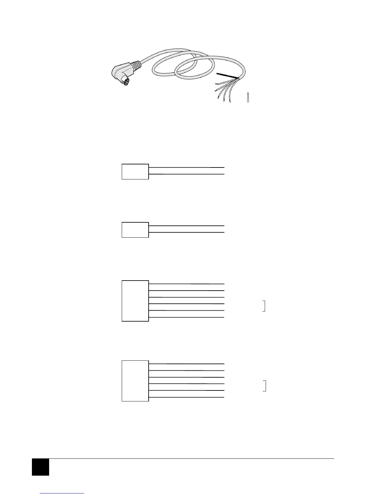
Figure 10: 07 SK 52 programming cable (grey)
07 SK 52 connection diagram (see Figure 10):
- Diagrams of RTS signal cabling:
If RTS is active at low level:
RTS+ 5
RTS- 8
CTS white
0V blue (for external GND)
central unit end
MIN DIN 8
bare wires end
If RTS is active at high level:
RTS+ 5
RTS- 8
+10 V white (for external DTR)
CTS blue
central unit end
MIN DIN 8
bare wires end
- Cable for RS 232
central unit end
MIN DIN 8
bare wires end
RxD 1
TxD 2
GND 7
RTS+ 5
RTS- 8
shield
TxD yellow
RxD red
GND black
white Cabling depends on if RTS is
blue active at high or low level
shield
- Cable for RS 485
central unit end
MIN DIN 8
bare wires end
1
D1- 2
D1+ 7
RTS+ 5
RTS- 8
shield
yellow not used
D1- red
D1+ black
white Cabling depends on if RTS is
blue active at high or low level
shield
Comment: The programming cable is distinguished from the ASCII/MODBUS
®
communication
cables by its grey colour.