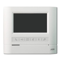
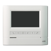
This document describes the ABB-Welcome Audio Handset Indoor Station, models M22001-, M22002-, and M22003-. It provides details on its function, technical specifications, usage, and installation.
Function Description
The ABB-Welcome Audio Handset Indoor Station is an integral part of the ABB Welcome door entry system. It is designed for indoor use and operates exclusively with other components of the ABB Welcome system. Its primary function is to facilitate communication with an outdoor station and control door access.
Important Technical Specifications
- Operating Temperature: -10°C to +55°C
- Storage Temperature: -40°C to +70°C
- Protection: IP 30
- Wiring:
- Single-wire clamps: 2 x 0.28 mm² - 2 x 1 mm²
- Fine-wire clamps: 2 x 0.28 mm² - 2 x 1 mm²
- Bus Voltage: 20-30 V
Usage Features
The indoor station offers several usage features, including:
Standard Operations
- Handset: Used to activate communication within 30 seconds of an incoming call and to end the call by hanging up.
- Unlock Button (2A): Allows the user to open the door at any time.
- Auto-unlock Function (2B): When activated (by holding the unlock button for over 10 seconds until the blue LED turns on), the door automatically opens for an incoming call. The same operation deactivates this function.
- Programmable Button (3A/3B):
- 3A: Can be programmed for additional functions such as calling a guard unit or intercom.
- 3B (Default): Releases the lock connected to an outdoor station (COM-NC-NO).
- Call Volume Adjustment (4): A three-level selector for adjusting the call volume (maximum, medium, or mute).
- LED Indicators:
- Red LED (5):
- Solid red: Indicates the door is open for a set time (requires a connected sensor).
- Flashing red: Indicates any button is pressed.
- No light: Indicates mute.
- Blue LED (6):
- Solid blue: Indicates the system is busy.
- Flashing blue: Indicates an incoming call.
- No light: Indicates auto-unlock is off.
- Induction Loop Function (7): Available only in M22003- models, this function requires contacting an electrical installer for use.
Settings
The device allows for customization of ringtones and programmable buttons.
- Ringtone Type Settings:
- Enter system setting mode by holding buttons "1" and "2" for approximately 3 seconds (blue and red LEDs flash simultaneously).
- Press the "unlock" button to cycle through ringtone types for the door bell.
- Press button "1" to cycle through ringtone types for calls from an outdoor station.
- Press button "2" to cycle through ringtone types for intercom calls from other apartments or the guard unit.
- Save settings and exit by holding buttons "1" and "2" for approximately 3 seconds.
- Default Outdoor Station Settings:
- Pick up the handset and hold the "unlock" button for approximately 3 seconds to enter default outdoor station setting mode.
- Press the "unlock" button to set the address of the default outdoor station (indicated by red LED flashes, settable from 1 to 9, default is 1).
- Save settings and exit by holding the "unlock" button for approximately 3 seconds or by placing the handset down.
- Programming Auxiliary Buttons:
- Enter programming mode by holding the programmable button for 3 seconds in standby mode.
- Set the function by checking the desired function and pressing button "1" to program the corresponding function code (indicated by blue LED flashes). Function codes cycle from 0 to 5.
- 0: No function (Blue LED always on)
- 1: Control switch actuator (Blue LED flashes once)
- 2: Intercom call in the same apartment (Blue LED flashes twice)
- 3: Intercom call among different apartments (Blue LED flashes 3 times)
- 4: Call guard unit (Blue LED flashes 4 times)
- 5: Release 2nd-lock of a default outdoor station (Blue LED flashes 5 times)
3. Set the address for functions 1 (Control switch actuator) and 2 (Intercom call among different apartments).
- Hold the programmable button for 3 seconds to enter address settings mode.
- Press the "unlock" button repeatedly to set the tens digit (indicated by red LED flashes).
- Press button "1" repeatedly to set the units digit (indicated by blue LED flashes).
- Digits can be changed in a sequence of 0->1->2->3->4->5->6->7->8->9->0.
- If the set value exceeds the desired number, pressing button "2" will reset both tens and units digits to 0.
4. Exit programming mode by holding the programmable button for 3 seconds (blue and red LEDs flash once simultaneously).
Adjusting the Device
- Jumper Settings (X100 X10 X1): Used to set the address of the indoor station (e.g., setting address 024).
- Master/Slave Function (M/S):
- Only one indoor station per apartment should be set as "Master" (Jumper 'M/S on').
- Additional indoor stations in the same apartment must be set as "Slave" (Jumper 'M/S off').
- Terminal Resistor (RC): In video or mixed audio/video installations, the jumper must be set to 'RC on' on the last device in the line.
- Bus Connection (a b): Indicates the bus connection.
- Door Bell Connection (1): Indicates the door bell connection.
Maintenance Features
The document primarily focuses on installation and usage, with limited explicit maintenance features. However, it emphasizes safety and proper disposal:
- Safety:
- Work on the 100-240V supply system must only be performed by authorized electricians.
- Disconnect mains power supply prior to installation or disassembly.
- Low-voltage and 100-240V cables must not be installed together in a flush-mounted socket to prevent hazards in case of a short-circuit.
- Environment Protection:
- Used electric and electronic devices must not be disposed of with domestic waste.
- The device contains valuable raw materials that can be recycled. Dispose of the device at an appropriate collecting depot.
- ABB products meet legal requirements, including EU-Directive 2002/96/EG WEEE and 2002/95/EG RoHS, and EU-REACH ordinance.
Installation
- Recommended Installation Height: 1.50 m (4.9 feet).
- Installation Dimensions: Provides diagrams for slotted screw holes (60mm width, 174mm height, 53mm depth, 79mm width for flush-mounted box).
- Wiring:
- Fix the bottom of the device to the wall or existing flush-mounted box.
- Connect wires according to the graphics, ensuring the insulated section of the cable end is no longer than 10mm.
- Latch the upper part of the device onto its bottom part by placing the upper side on the lock-in lugs and pressing the bottom side until it is caught by the clamp.
- General Installation Instructions:
- Terminate all wiring system branches via a connected bus device.
- Do not install the system controller directly next to bell transformers or other power supplies to avoid interference.
- Do not install system bus wires together with 100-240V wires.
- Do not use common cables for door opener wires and system bus wires.
- Avoid bridges between different cable types.
- Use only two wires for the system bus in a four-core or multi-core cable.
- When looping, never install incoming and outgoing bus inside the same cable.
- Never install the internal and external bus inside the same cable.
- Requirements for the Electrician:
- Install the device only with necessary electrical engineering knowledge and experience.
- Incorrect installation endangers life and property.
- Apply the "five safety rules" (DIN VDE 0105, EN 50110): Disconnect from power, secure against re-connection, ensure no voltage, connect to earth, and cover/barricade adjacent live parts.
- Use suitable personal protective clothing, tools, and measuring devices.
- Check the type of supply network (TN, IT, TT system) to ensure proper power supply conditions.