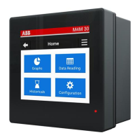
M4M 30 NETWORK ANALYZER USER MANUAL
19
Inputs and outputs connections
• Programmable I/O: Alarm output with external relays for load command. Example of wiring for I/O1 as
alarm output, COM is common for all I/O:
A: V aux 48 V a.c./d.c. 100mA
B: External relay
• Programmable I/O: Pulse output. Example of wiring for I/O1 as pulse output, COM is common for all
I/O:
A: V aux 48 V a.c./d.c. 100mA
C: Pulse acquisition
• Programmable I/O: Tariff input. Please note that only I/O1, I/O2, I/O3 can be used as tariff inputs.
Example of wiring for I/O1 as tariff input, COM is common for all I/O:
A: 24-240VDC / 57-240VAC
B: Tariff acquisition
• Programmable I/O: Pulse input for external pulse acquisition. Example of wiring for I/O1 as pulse input,
COM is common for all I/O:
A: 24-240VDC / 57-240VAC
B:
Pulse acquisition (Impulse length at least 30 mS )
Same wiring schemes apply for I/O5 and I/O6 available only on M4M 30 I/O.
• Analogue outputs, typical load 250 Ohm, max 500 Ohm (available only on M4M 30 I/O):


 To Next Page