-- 8 --
ba39d1ea
5.3 Mains power supply
Check that the welding power source is connected to the
correct mains power supply voltage, and that it is protected by
the correct fuse size. A protective earth connection must be
made in accordance with regulations.
Rating plate with supply connection data
Recommended fuse sizes and minimum cable area
MigRob 500 400 V 3μ 50 Hz
Mains voltage 400 V
Mains cable area mm
2
4G6
Phase current, IRMS 31 A
Fuse
Anti--surge
Type C MCB
35 A
40 A
Note! The mains cable areas and fuse sizes as shown above are in accordance with Swedish
regulations. Use the welding power source in accordance with the relevant national regulations.
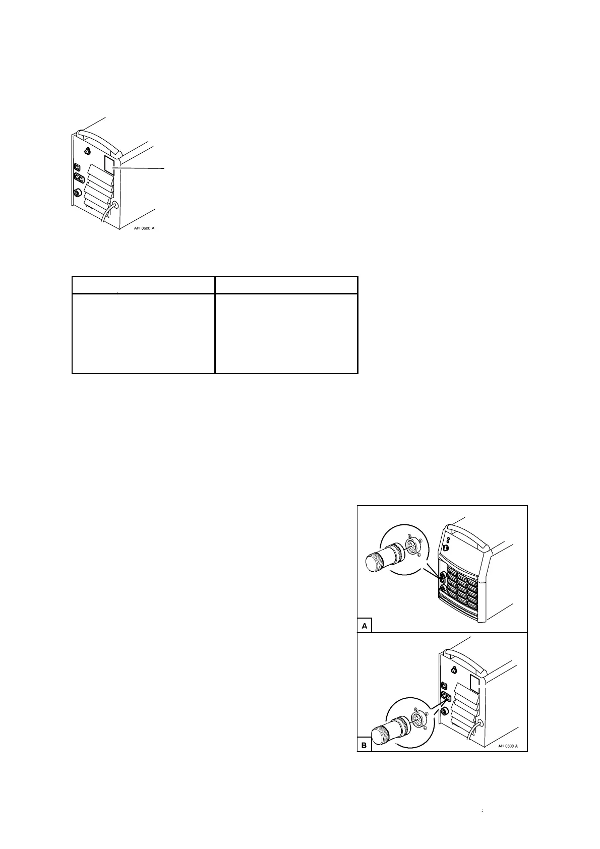
5.4 Terminating resistors
The ends of the CAN bus must be fitted with terminating resistors to avoid
communication interference.
Inte rn al CAN--bus
One end of the CAN--bus is at the welding data unit,
which has an integral resistor. The other end is at the
power source and must be fitted with the terminating
resistor, as shown in figure A.
External CAN--bus
The power source has two connections for the
external CAN--bus, ”EXT CAN IN” and
”EXT CAN OUT”.
The cable from the robot system is connected to the
connector m arked ”EXT CAN IN”. If the power
source is located at the end of the CAN--bus, the
terminating resistor must be located in ”EXT CAN
OUT” in accordance with figure B. If the power
source is not the final unit on the CAN--bus, ”EXT
CAN OUT” is u sed to connect the bus on to
additional CAN units (in such cases the terminating
resistor is placed in the final unit on the bus.)