-- 9 --
ba39d1ea
6 OPERATION
General safety regulations for the handling of the equipment can be found on
page 4. Read through before you start using the equipment!
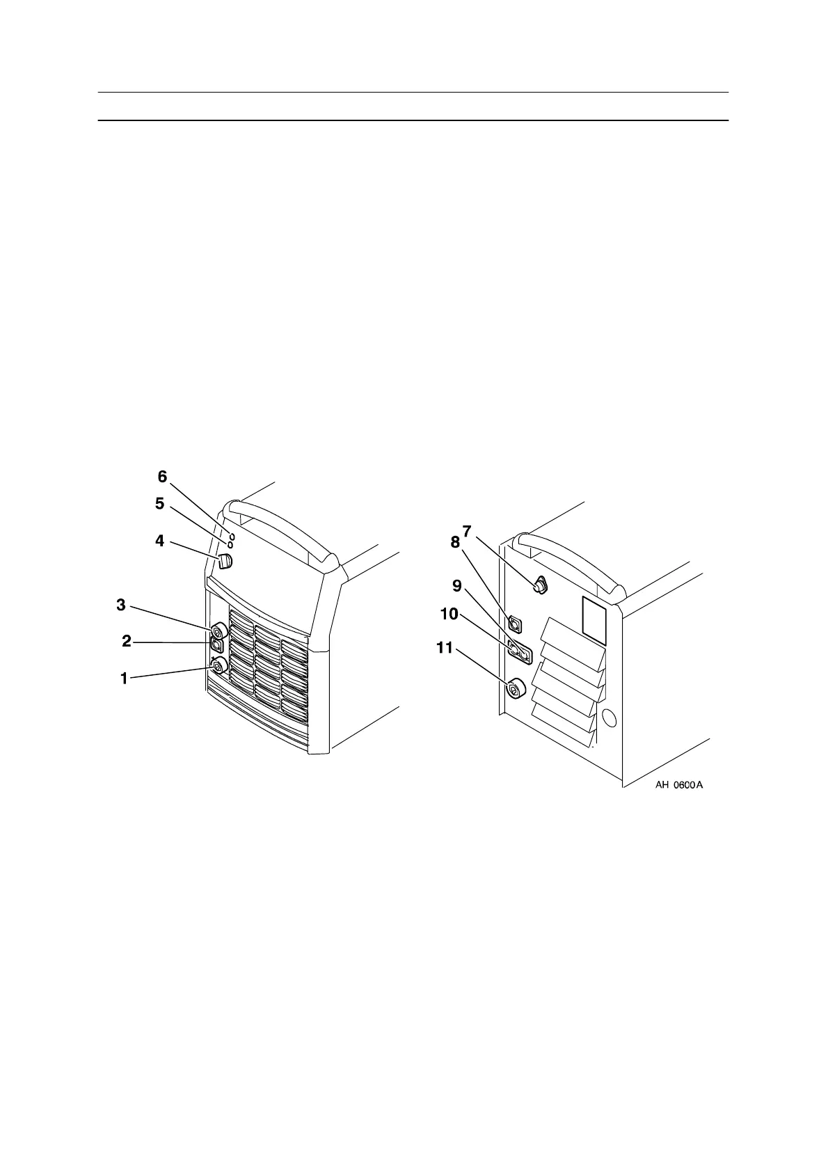
6.1 Connections and control devices
1 Connection for welding current cable (+) 7 Fuse, 4 A
2 Connection for terminating resistor, 42 V,
Internal CAN--bus.
8 Connection measurement cable, (arc
voltage detection welding wire /
workpiece), MEASURE
3 Connection for return cable (--) 9 Connection for terminating resistor,
EXTERN CAN OUT
4 Mains power supply switch, 0 / 1 / START 10 Connection for communication with robot
system, EXTERN CAN IN
5 White indicating lamp – Power supply ON 11 Connection for welding current cable (+)
6 Orange indicating lamp – Overheating
6.2 Turning on the power source
Turn on the mains power by turning switch (4) to the ”START” position. Release the
switch, and it will return to the ”1” position.
If the mains power supply should be interrupted while welding is in progress, and
then be restored, the power unit will remain de--energised until the switch is again
turned manually to the ”START ” position.
Turn the unit off by turning the switch to the ”0” position.
Whether the mains power supply is interrupted or the power unit is switched off in
the nor mal manner, welding data will be stored so that it is available next time the
unit is started.