8 MNS-MCC LOW VOLTAGE MOTOR CONTROL CENTER
MNS-MCC Standard configuration structure
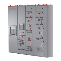
The MCC assembly consists of one or more metal
enclosed vertical sections. Each vertical section
has an internal framework for mounting one or
more units, and a bus compartment in the rear
of the section. A continuous horizontal ground bus
is located at the bottom of all section.
End sections are designed to allow for the addition
of future sections. The MCC may accept cable entry
fromthe top, bottom or both. Lifting angles are
provided to allow lifting by crane. See “Crane
Handling”. There is an additional 50mm (1.97in)
added to the total height by them.
—
01 MCC Configuration
Top cover
Lifting angles
Horizontal Neutral
Bar (Option)
Main Horizontal
Bus Bar
2nd Horizontal
bus bars set
(Where needed)
Vertical wireway/door
Bottom plate
(Optional)
splice connection
point zontal Bus Bar
Top Horizontal
Wireway / Door
Modular fixed unit
Multi-function Wall
Compartment
bottom plate
Withdrawable unit
Bottom horizontal
wireway/door
Horizontal ground bar
—
01