Appendix C – Technical Data
NPBA-12 Installation and Start-up Guide C-3
NPBA-12
Enclosure: Plastic, dimensions 100 × 22.5 × 115 mm (H×W×D);
degree of protection IP 20
Mounting: Onto a standard mounting rail
Settings: Via drive interface (control panel)
Current Consumption: 70 mA at 24 V d.c.
Connectors:
• Light transmitter (grey) and receiver (blue) (Hewlett-Packard
Versatile Link) for connection to the drive
• Two Combicon MSTBT 2,5/4-ST (4-pole, cross-section
2.5 mm
2
max.) screw terminal blocks for the fieldbus and power
supply connections:
General:
• All materials are UL/CSA approved
• Complies with EMC Standards EN 50081-2 and EN 50082-2
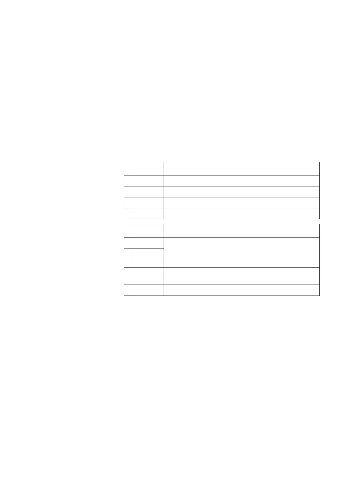
X1 Description
1 A Data Negative (Conductor 2 in twisted pair).
2 B Data Positive (Conductor 1 in twisted pair).
3 A Data Negative (Conductor 2 in twisted pair).
4 B Data Positive (Conductor 1 in twisted pair).
X2 Description
5 +24V Power supply for the module (24 V d.c. ±10%).
The power can be taken from the drive’s internal power supply
(see drive manuals), or an external power supply.
On-board power supply shuts off if the voltage drops below 11 V.
60V
7 DG PROFIBUS cable data ground (optional 3rd conductor).
Connected to module earth via a 1 MΩ/15 nF RC network.
8 SH PROFIBUS cable shield. Internally connected to module earth.