ODIN Meter
Installation and Operating Instructions
Introduction
The ODIN-Meter is a compact, electronic electri-
city meter for DIN rail mounting in distribution
boards or small enclosures. The devices are
designed to measure active energy in 230 VAC,
4 wire polyphase networks with symmetric or
asymmetric loading.
Installation
Follow the instructions in this instruction leaflet and
those on the meter carefully. Do not operate the
ODIN-Meter outside of the specified technical data.
Installation and commissioning may only be carried
out by authorised electrical specialists. The in-
staller is responsible that the electricity meter is
correctly and safely installed.
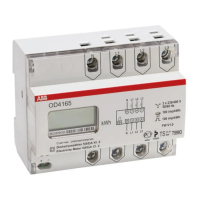
Direct connected meter (e.g. OD4165)
1 Mount the electricity meter on the DIN rail.
1.1 Strip the cable insulation according to recom-
mended length.
1.2 Connect the electricity meter according to the
wiring diagram on the front of the device. The
recommended tightening torque of the connection
terminals is 2 Nm. A no. 2 pozidrive screwdriver is
required.
1.3 Circuit protection for the electricity meter must
be installed: max. 63 A (MCB C characteristic or
fuse gLgG).
1.4 Check that the electricity meter is correctly
installed and connected to the specified voltage
before switching the power on.
1.5 To confirm correct operation of the electricity
meter while under real loading conditions, check
that the phase voltage indicators L1, L2, and L3 can
all be seen and are not flashing and that the load
indicator in the display is rotating.
Transformer rated meter (e.g. OD4110)
2 Mount the electricity meter on the DIN rail.
2.1 Strip the cable insulation according to recom-
mended length.
2.2 Connect the electricity meter according to the
wiring diagram on the front of the device. The
recommended tightening torque of the voltage
connection terminals is 1 Nm and of the current
connection terminals 2 Nm. A no. 1 and a no. 2
pozidrive screwdriver are required.
2.3 Circuit protection for the voltage inputs of the
electricity meter must be installed: max. 10 A (MCB
B characteristic or fuse gLgG).
2.4 Check that the electricity meter is correctly
installed, connected to the specified voltage and
that the polarity of the external current transformers
is correct before switching the power on.
2.5 Set the current transformer ratio (as shown on
the current transformer) 5/5A .....900/5A by pressing
the button situated on the front of the electricity meter
until the correct ratio is visible on the display.
After the current transformer ratio has been program-
med the electricity meter displays the true (primary)
energy consumption.
2.6 To confirm correct operation of the electricity
meter while under real loading conditions, check
that the phase voltage indicators L1, L2, and L3 can
GB
10