EasyManuals Logo

ABB PGC5000 User Manual

ABB PGC5000
17 pages
To Next Page IconTo Next Page
To Previous Page IconTo Previous Page
Page #13 background imageLoading...
Page #13 background image
892J009MNAE | DBDID | 13
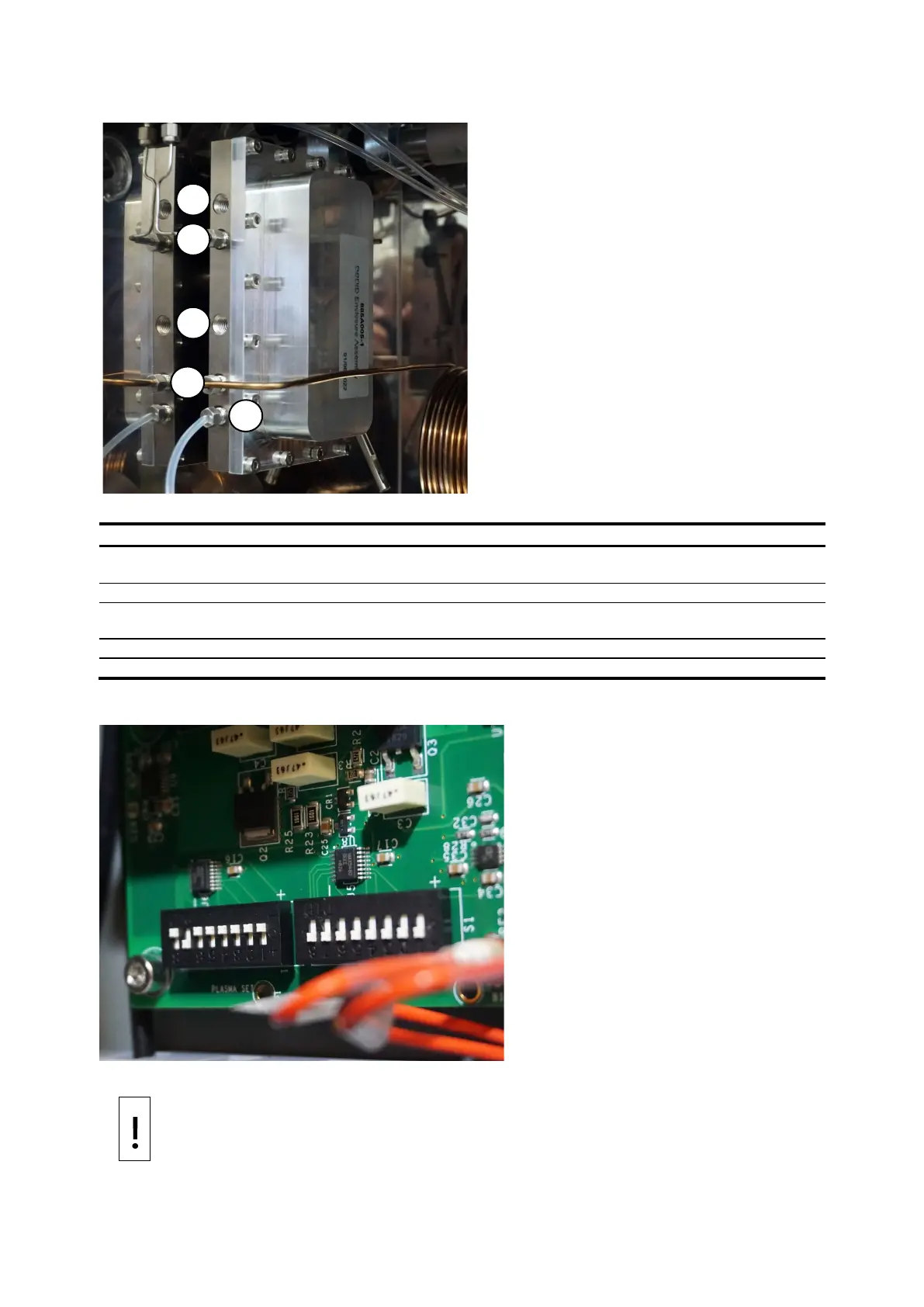
Figure 5-1: Detector port identification
1
2
3
4
5
Legend: Detector port identification
Item
Description
1
Purge gas inlet. (Detector assembly purge not used in most applications.)
Flameproof breather must remain open or connected to optional purge system.
2
Reaction gas inlet (plasma gas)
3
Purge gas vent. (Detector assembly purge not used in most applications.)
Flameproof breather must remain open or connected to optional purge system
4
Detector inlet (chromatograph column connection for analytes to the detector)
5
Detector vent
Figure 5-2: Power supply dip switch settings
NOTICE
Equipment damage. Dip switches on the power supply should never be
adjusted without factory support
.

Questions and Answers:

Question and Answer IconNeed help?

Do you have a question about the ABB PGC5000 and is the answer not in the manual?

ABB PGC5000 Specifications

General IconGeneral
Analysis TypeGas Analysis
CommunicationEthernet
Accuracy±1% of full scale
Output Signal4-20 mA
Power Supply100-240 VAC, 50/60 Hz
Enclosure RatingIP65 / NEMA 4X
Measurement PrincipleParamagnetic for O2, Zirconia for O2, Infrared for CO/CO2, Electrochemical for other gases

Related product manuals