EasyManuals Logo

ABB PGC5000 User Manual

ABB PGC5000
17 pages
To Next Page IconTo Next Page
To Previous Page IconTo Previous Page
Page #7 background imageLoading...
Page #7 background image
892J009MNAE | DBDID | 7
Legend: Disconnect lines
Item
Description
1
Reaction gas inlet (plasma gas)
2
Detector inlet (chromatograph column connection for analytes to the detector)
3
Detector vent
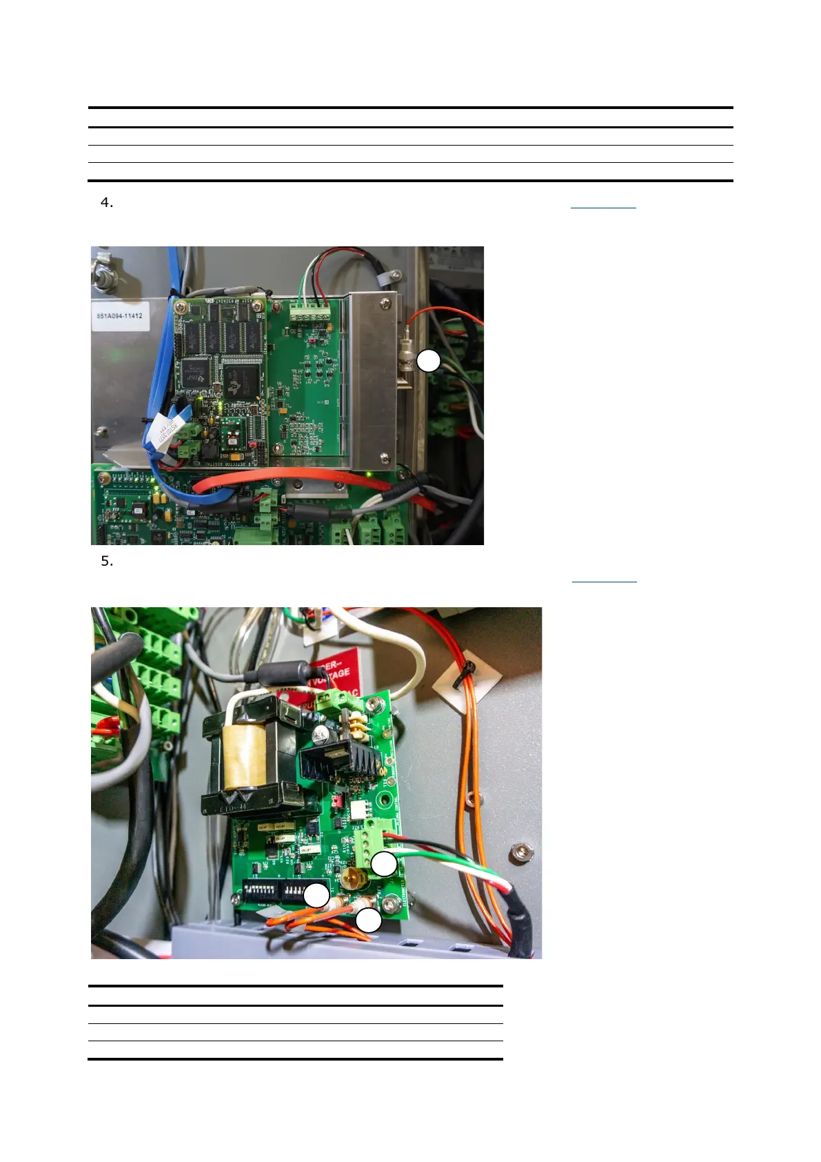
Open the left side oven door and disconnect the coax cable (item 1 in Figure 2-3) from the
DBDID amplifier assembly.
Figure 2-3: DBDID amplifier assembly
1
On the DBDID power supply board, unplug the high voltage power connector (J2) (item 3), the
bias cable (RF2) (item 1), and the feedback cable (RF1) (item 2). See
Figure 2-4.
Figure 2-4: DBDID power supply board
3
1
2
Legend: DBDID power supply board
Item
Description
1
Bias cable (RF2)
2
Feedback cable (RF1)
3
High voltage power connector (J2)

Questions and Answers:

Question and Answer IconNeed help?

Do you have a question about the ABB PGC5000 and is the answer not in the manual?

ABB PGC5000 Specifications

General IconGeneral
Analysis TypeGas Analysis
CommunicationEthernet
Accuracy±1% of full scale
Output Signal4-20 mA
Power Supply100-240 VAC, 50/60 Hz
Enclosure RatingIP65 / NEMA 4X
Measurement PrincipleParamagnetic for O2, Zirconia for O2, Infrared for CO/CO2, Electrochemical for other gases

Related product manuals