15
kV Isc Icw W=600 W=750 W=750 W=750 Interruttore PowerCube
(kA) (kAx3s) p=150 p=210 p=210 p=210 Circuit-breaker
u/l=205 u/l=310 u/l=310 u/l=310
H=260 H=280 H=280 H=325
ø=35 ø=35 ø=79 ø=35
12 16 16 630 VM1/P 12.06.16 p150 VM1/P 17.06.16 p150 PB 1/F
17,5 (1) 20 20 630 VM1/P 12.06.20 p150 VM1/P 17.06.20 p150
25 25 630 VM1/P 12.06.25 p150 VM1/P 17.06.25 p150
31,5 31,5 630 VM1/P 12.06.32 p150 VM1/P 17.06.32 p150
16 16 1250 VM1/P 12.12.16 p150 VM1/P 17.12.16 p150
20 20 1250 VM1/P 12.12.20 p150 VM1/P 17.12.20 p150
25 25 1250 VM1/P 12.12.25 p150 VM1/P 17.12.25 p150
31,5 31,5 1250 VM1/P 12.12.32 p150 VM1/P 17.12.32 p150
16 16 630 VM1/W 12.06.16 p210 VM1/W 17.06.16 p210 PB 2/F
20 20 630 VM1/W 12.06.20 p210 VM1/W 17.06.20 p210
25 25 630 VM1/W 12.06.25 p210 VM1/W 17.06.25 p210
31,5 31,5 630 VM1/W 12.06.32 p210 VM1/W 17.06.32 p210
16 16 1250 VM1/W 12.12.16 p210 VM1/W 17.12.16 p210
20 20 1250 VM1/W 12.12.20 p210 VM1/W 17.12.20 p210
25 25 1250 VM1/W 12.12.25 p210 VM1/W 17.12.25 p210
31,5 31,5 1250 VM1/W 12.12.32 p210 VM1/W 17.12.32 p210
20 20 1600 VM1/P 12.16.20 p210 VM1/P 17.16.20 p210
25 25 1600 VM1/P 12.16.25 p210 VM1/P 17.16.25 p210
31,5 31,5 1600 VM1/P 12.16.32 p210 VM1/P 17.16.32 p210
20 20 2000 VM1/P 12.20.20 p210 VM1/P 17.20.20 p210
25 25 2000 VM1/P 12.20.25 p210 VM1/P 17.20.25 p210
31,5 31,5 2000 VM1/P 12.20.32 p210 VM1/P 17.20.32 p210
24 (1) 16 16 630 VM1/P 24.06.16 p210 PB 4/F
20 20 630 VM1/P 24.06.20 p210
25 25 630 VM1/P 24.06.25 p210
16 16 1250 VM1/P 24.12.16 p210
20 20 1250 VM1/P 24.12.20 p210
25 25 1250 VM1/P 24.12.25 p210
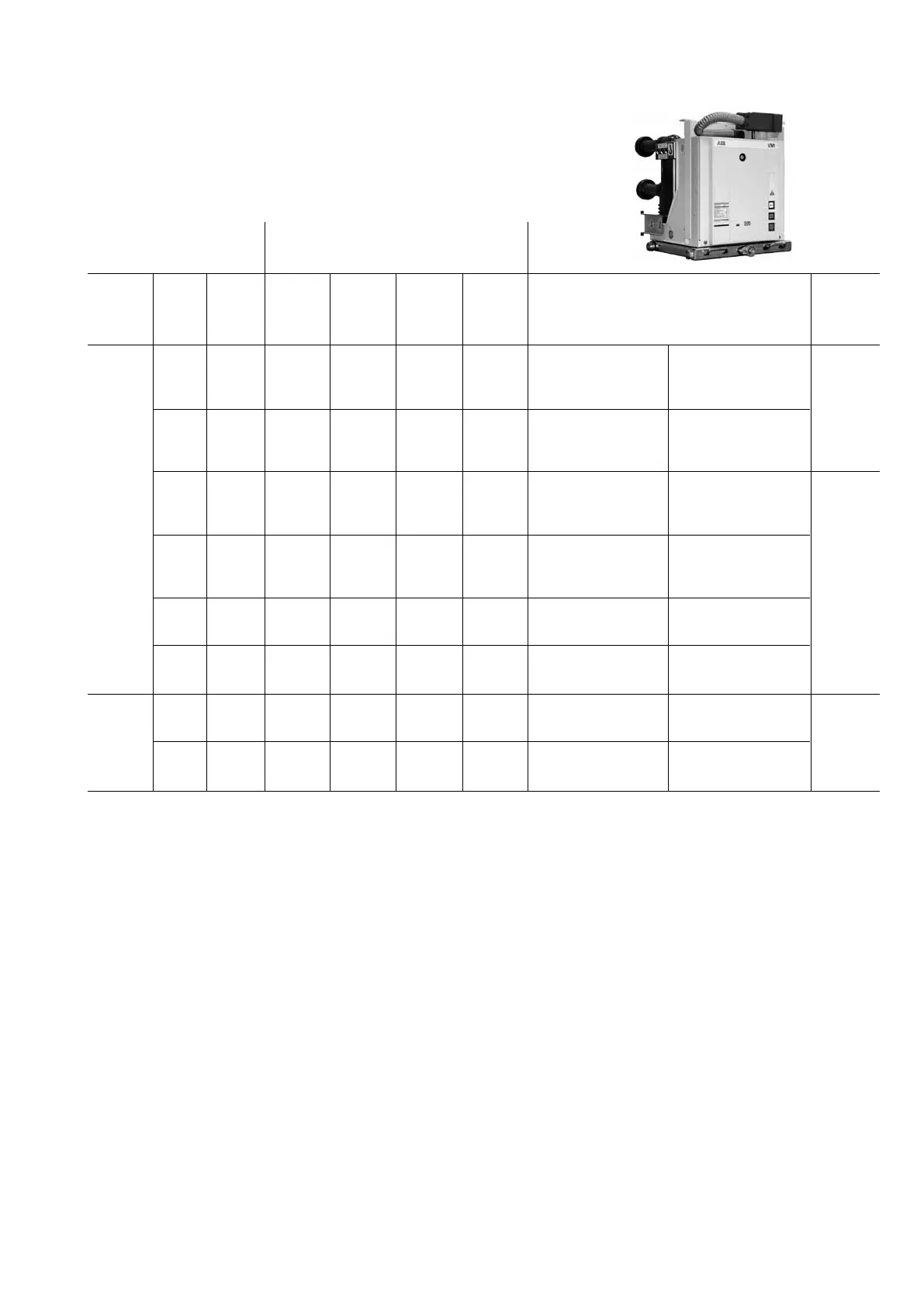
Corrente nominale
degli interruttori VM1 (A - 40 °C)
Rated current of the
circuit-breakers VM1 (A - 40 °C)
Tab. 3 - Interruttori estraibili VM1 (*) Table 3 - Withdrawable VM1 circuit-breakers (*)
W = Larghezza Modulo PowerCube.
P = Interasse orizzontale tra i poli dell’interruttore.
U/L = Distanza tra terminale superiore ed inferiore.
H = Distanza tra terminale inferiore e terra
Ø = Diametro dei contatti presenti nel monoblocco del modulo PowerCube.
(*) Le parti fisse non sono predisposte per l’applicazione “carrello motorizzato”.
W = Width of PowerCube module.
P = Horizontal centre distance between circuit-breaker poles.
U/L = Distance between top and bottom terminal.
H = Distance between bottom terminal and earth.
Ø = Diameter of the contacts in the PowerCube module monobloc.
(*) The fixed part are not prepared for application of the “motorised truk”.

 Loading...


