Chapter 6
Human-Machine Interface (HMI)
This chapter describes how the human-machine interface (keypad and display) works.
6:1 Overview
6:1.1 Application
The Human-Machine Interface is used for several purposes such as programming the softstarter, i.e setup of
inputs and outputs, protection functions, warning levels, eldbus communication, etc. The HMI is also used for
monitoring, local control and receiving status information from the softstarter.
6:1.2 Design
The HMI consists of:
• Status indication
LED indicators
• LCD display
• Selection and Navigation keys
The LED indicators work as follows:
LED Color Description
Power on Green Control voltage connected
Fault Red Indicates faults
Protection Yellow Indicates protective function has activated
When a Fault or Protection LED is activated, the LCD displays the actual fault or protection.
The keypad is based on the same user concept as today’s mobile phones.
The LCD contains two rows with 20 characters each.
The top row presents various information depending on its state. The bottom row indicates which function is
currently selected.
A scrolling icon indicates what parameter or setting value is possible to change at the position.
The
Selection keys normally have more than one function, such as selecting, changing and storing parameters.
See the text on the bottom row of the LCD.
The
Navigation keys are used for navigating through the various menus to the desired setting.
When selecting from a list, the scrolling is done in a closed loop fashion.
The functionality of the keypad is illustrated by the following example:
Changing the rated motor current (
Setting I
e
).
1. You will nd the setting as well as a short explanation and the path to it in Chapter 10 “ Functions”.
Path in menu:
Menu/SETTINGS/Functional Settings/
Start/Stop /Setting Ie
2. The top level of the softstarter start menu looks as in Figure 3. Press the left selection key to enter the menu.
The display now appears as in Figure 4.
3. Press the left selection key to select
SETTINGS. The display appears as in Figure 5.
4. Press the lower navigation key until the display appears as in Figure 6.
5. Press the left selection key to select Functional settings
. Press the left selection key to select Start/Stop,
Figure 7.
6. Press the left selection key to
Change the Setting Ie, Figure 8.
The display now appears as in Figure 9.
7. Use the navigation keys to set the rated current. If you want to quit, you select
Cancel, using the right selec-
tion key. Otherwise, you store the new setting by selecting Store with the left selection key. The display should
now appear as in Figure 10.
8. Press the right selection key four times to return to top level.
Power on ProtectionFault
1
2
3
4
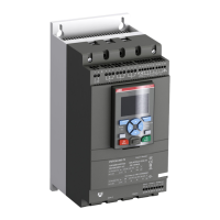
Figure 1: Human-Machine Interface
1 Status indication LEDs
2 LCD display
3 Selection keys
4 Navigation keys
Figure 2: Menu examples
1 Scrolling icons
Power on ProtectionFault
Power on ProtectionFault
1
1
Setting Ie 100A
Change Back
Setting Ie 100A
Store Cancel
Setting Ie 99.5A
Change Back
Figure 10: Setting Ie menu, changing setting
Setting Ie 100A
Store Cancel
Figure 9: Setting Ie menu, changing menu
Setting Ie 100A
Change Back
Figure 8: Setting Ie menu
Figure 7: Start/stop menu
Functional Settings
Select Back
Figure 6: Functional settings menu
Application Setting
Select Back
Figure 5: Application Setting menu
Figure 4: SETTINGS menu
Figure 3: Top level
6.2 Low Voltage Products & Systems
1SXU 132 021 M0201 ABB Inc. • 888-385-1221 • www.abb-control.com
6

 Loading...