Do you have a question about the ABB PSTX 570 and is the answer not in the manual?
Explains the warning and information signs used in the manual for user attention.
Details precautions for handling sensitive electronic components to prevent ESD damage.
Provides guidelines for ensuring personal safety during maintenance operations.
Provides an overview of the service manual's purpose, scope, and intended audience.
Lists and defines common acronyms and abbreviations used throughout the manual.
Details the steps for routine maintenance and checks of the Softstarter.
Lists the essential tools needed for performing service and repair tasks.
Guidelines and resources for performing service and repair on the Softstarter.
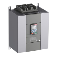
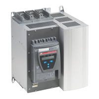
Identifies product labels, terminal markings, and connection points.
Step-by-step instructions to access the Softstarter's service parameters.
Procedures for updating firmware, setting the ID, and resetting the HMI.
Safe procedures for disconnecting main power and control cables before service.
Detailed guide for servicing and replacing the Printed Circuit Board Assembly (PCBA).
Procedure for safely replacing the Silicon Controlled Rectifier (SCR) component.
Instructions on how to perform tests on the SCR to detect faults.
Provides the electrical schematic diagram for the IEC version of the Softstarter.
Provides the electrical schematic diagram for the UL version of the Softstarter.
| Rated Operational Current - In Line Connection (Ie) | 570 A |
|---|---|
| Overload Protection | Yes |
| Degree of Protection | IP20 |
| Rated Operational Voltage | 200-690V AC |
| Rated Control Supply Voltage (Us) | 100-240V AC/DC |
| Starting Capacity at Maximum Rated Current Ie | 10s |
| Step Down Voltage Ramp | Adjustable |
| Initial Voltage Ramp | Adjustable |
| Current Limit During Start | Adjustable |
| Built-in Bypass | Yes |
| Communication | Modbus RTU, Profibus |
| Input voltage range | 200-690V AC |
| Output voltage | 200-690V AC |