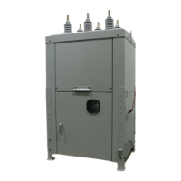
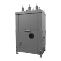
6.2 Opening
When the bottom coil is energized, the magnetic flux opposes the force generated by the magnet
assembly. This reduces the holding force, the armature is released and the coil attracts the arma-
ture to the bottom plate. Once there, it is held open by the magnet.
7.0 OPERATIONAL CHECK PRIOR TO INSTALLATION
The breaker should be tested for mechanical and electrical operation before delivery to the installa-
tion site. Make the necessary control power connections. Open the door of the low voltage com-
partment to observe the mechanical operations. A manual trip handle is provided on the outside of
the cabinet. (See Figure 10)
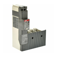
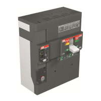
7.1 Electrical Close and Open
Observe the position-indicator located on the front of the actuator cover plate. If the panel is green,
the breaker is open, and if the panel is red, the breaker is closed. To perform a close or open,
ensure the “Ready” light is illuminated above the Close (1) and Open (0) buttons. Press the appro-
priate button firmly, keeping hands and loose clothing clear of operating linkages. If the breaker is
already open, nothing will happen when the open button is pressed. If the breaker is already
closed, nothing will happen when the close button is pressed.
Note: In the event of a malfunction or loss of source voltage, the “Ready” light will not be illuminat-
ed.
7.2 Vacuum Test
Perform an over-voltage test on each phase assembly to verify that there has been no loss of vac-
uum in transportation or handling. Experience has shown that a vacuum interrupter with the vacu-
um seal intact will withstand 37.5 kVAC across the open contacts for one minute, and the same
vacuum interrupter open to normal atmosphere will flashover at the gap at a much lower voltage.
TEST PROCEDURE
RADIATION WARNING: High voltage applied across an open gap in a vacuum can produce X-
radiation. No radiation is emitted when the interrupter is closed, since no gap exists. Also, when the
breaker is open to the specified contact spacing in service or tested within the voltages specified,
X-radiation at one meter is below the level of concern. A danger could exist at voltages above or
contact spacing below that specified on the nameplate.
1. With the breaker in the open position, jumper both sets of three top terminals together. Ground
one set of terminals and the housing. Connect the high voltage to the other set of terminals.
2. Stand clear more than one meter before energizing the high voltage source.
3. Apply a test voltage of 37.5 kVAC for one minute. Do not exceed 37.5 kVAC.
4. If internal flashover occurs, isolate the phases and test each one independently to identify the
defective interrupter. Any defective interrupter must be replaced prior to the breaker being
placed in service.
7