Do you have a question about the ABB R-MAG Series and is the answer not in the manual?
Inspect equipment upon receipt for correctness and damage.
Instructions for safely lifting and moving the breaker using brackets.
Recommendations for proper storage to maintain warranty and prevent condensation.
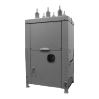
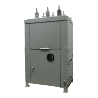
Describes the high-voltage section with phase assemblies and vacuum interrupters.
Details the breaker housing, removable doors, and nameplate location.
Explains the components of a phase assembly, including vacuum interrupter and bus connections.
Describes the powerful permanent magnet assembly and its operation.
Overview of the ED2.0 control package including power supply and indicator systems.
Explains the sequence of events and forces involved when closing the breaker.
Describes the process and forces involved when opening the breaker.
How to perform and observe electrical close and open operations.
Procedure for testing vacuum integrity of phase assemblies.
Recommended procedure for mounting the breaker in a substation.
Guidelines for grounding the breaker cabinet and associated components.
ABB's recommendation for applying surge arresters.
Information on supplying control power and checking connections.
Checklist for final inspection before energizing the power line.
Detailed steps for replacing a vacuum interrupter unit.
Procedures for adjusting contact travel and over-travel.
Introduction to the ED2.0 electronic control board and its components.
Lists available ED2.0 boards and capacitor specifications.
Key features and functionalities of the ED2.0 control board.
Functionality of the open lock feature for service or maintenance.
Description of the temperature monitoring and protection circuit.
Explanation of fast and slow input signal response times.
Monitor for continuity of actuator close and trip coils.
Automatic trip if a close operation fails within a specified time.
Auto trip function when capacitor voltage falls below a threshold.
Setting to lower power output and its implications.
Use of the RS232 port for software download and upgrades.
Use of the JTAG port for software debug and upgrades.
Details on the different types of binary inputs and their functions.
Function and impedance of the remote open input.
Function and impedance of the remote close input.
Function and impedance of the auxiliary open input.
Function and priority of the safe open input.
Input for special protection relay requirements.
Function and impedance of the second trip input.
Feature to lock the breaker open for maintenance.
Auto trip function based on monitored voltage levels.
Description of binary outputs and their functions.
Output contacts indicating the breaker is open.
Output contacts indicating the breaker is closed.
Auxiliary output contacts for open breaker status.
Auxiliary output contacts for closed breaker status.
Output indicating the unit is ready for operation.
Output indicating the unit is not ready.
Fleeting output contacts for remote open operations.
Information on power supply, capacitor voltage, and operation thresholds.
Procedure for safely discharging storage unit capacitors.
Expected operational life and replacement recommendations for capacitors.
Flowcharts to help diagnose and resolve operational issues.
Diagram illustrating the ED2.0 circuit board layout and connections.
Detailed listing of connectors and their pin assignments on the ED2.0 board.
Connector for magnetic actuator position sensing.
Connector for power output and capacitor connections.
Connector for auxiliary supply and capacitor connections.
Connector for general purpose binary output contacts.
Connector for general purpose binary inputs.
Connector for future use with pressure LED indicators.
Connector for the membrane local control switch.
Connector for JTAG emulation interface.
Connector for RS232 download interface.
Connector for analog board to mother board connection (future design).
Setting for Under Voltage threshold.
Setting for input response delay and input mode.
Settings for low energy trip and UV delay functions.
Default configurations for jumpers and dip switches.
Default setting for JP1001 for Auxiliary/Protection Relay input.
Default settings for Dip Switch 11001 (Under Voltage Range).
Default settings for Dip Switch 11002 (Fast/Slow Input).
Default settings for Dip Switch 11004 (Low Energy Trip/UV Delay).
| Category | Circuit Breakers |
|---|---|
| Breaking Capacity | Up to 36 kA |
| Trip Unit | Thermal-Magnetic |
| Series | R-MAG |
| Rated Voltage | 690 V |
| Voltage Rating | 690 V |
| Poles | 1, 2, 3, 4 |
| Standards | IEC 60947-2 |
| Rated Current | 0.5A to 63A |
| Current Rating | 0.5A to 63A |