TEST PROCEDURE
RADIATION WARNING: High voltage applied across an open gap in a vacuum can produce
X-radiation. No radiation is emitted when the interrupter is closed since no gap exists. Also,
when the breaker is open to the specified contact spacing in service or tested within the
voltages specified, X-radiation at one meter is below the level of concern. A danger could
exist at voltages above or contact spacing below that specified on the nameplate.
1. With the breaker in the open position, jumper both sets of three top terminals together.
Ground one set of terminals and the housing. Connect the high voltage to the other set of
terminals.
2. Stand clear more than one meter before energizing the high voltage source.
3. Apply a test voltage of 37.5 kVAC for one minute. Do not exceed 37.5 kVAC.
4. If internal flashover occurs, isolate the phases and test each one independently to
identify the defective interrupter. Any defective interrupter must be replaced prior to the
breaker being placed in service.
8.0 INST
ALLATION
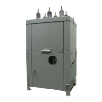
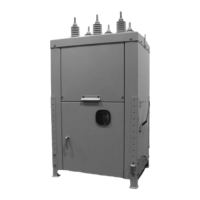
It is required that the breaker be vertical and level, and securely fastened. Follow your
company guidelines and various codes for setting the height of the breaker, securing the
frame to the pole or foundation, and for making connections.
8.1 Mounting
The breaker is normally shipped suitable for substation mounting. The following is the
recommended installation procedure:
Substation Mounting
1. With the lifting brackets mounted to the breaker roof, lift the breaker off the pallet and
move into position.
2. Bolt the legs to the pad, and raise the upper portion to the desired height.
3. Bolt legs to the sides of the breaker.
4. Make sure all hardware is tight.
Page 6
38-929M-15A 10/15/02 1:11 PM Page 10
 Loading...