1MRS750527-MUM
REF 54_
75
Feeder Terminal
Technical Reference Manual, General
A050742
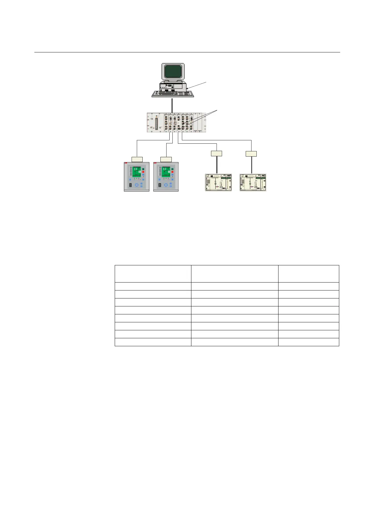
Fig. 5.1.13.9.-1 Example of a LON-based substation automation system
In the system described in the figure above, communication is usually arranged as
shown in the table below.
Other supported system configurations are represented in the following figures. A
LON bus and a parallel “SMS” bus connected as a SPA loop using the interface
module RER 123 on connector X3.2, allows to implement the redundant SMS
workstation.
Table 5.1.13.9-1 Communication arrangement example
Data type REF <-> MicroSCADA
REF and LSG
devices to each other
Control commands transparent SPA bus messages -
Events and alarms sliding window protocol -
State of breakers and isolators sliding window protocol network variables
Analog measurement values sliding window protocol -
Other DI, AI data sliding window protocol network variables
Other DO, AO data transparent SPA bus messages network variables
Parameter data transparent SPA bus messages -
SPA file transfer data transparent SPA bus messages -
O
I
SPAC 331 C
REF 541
Uaux = 80...265 Vdc/ac
fn = 50 Hz
In = 1/5 A (I)
1MRS xxxxxx
98150
9509
Ion = 1/5 A (Io)
Un = 100/110 V (U)
Uon = 100/110 V (Uo)
21 kV
CB OK
AROFF
REF 541
Uaux = 80...265 Vdc/ac
fn = 50 Hz
In = 1/5 A (I)
1MRS xxxxxx
98150
9509
Ion = 1/5 A (Io)
Un = 100/110 V (U)
Uon = 100/110 V (Uo)
21 kV
CB OK
AROFF
O
I
SPAC 331 C
SPA bus modules connected
over LON/SPA-gateways
RE_ 54_ terminals
connected via RER 103
fibre-optic adapters
RER 111 LON
star-coupler
SPA bus
SPA bus
Fibre-optic
LON network
MicroSCADA
PCLTA card and
RER 107 inside PC
RER 111 LON
SFIBER connection
cards