64
1MRS750527-MUM
)HHGHU7HUPLQDO
Technical Reference Manual, General
5()B
In the system described in the figure above, communication is usually arranged as
shown in the table below.
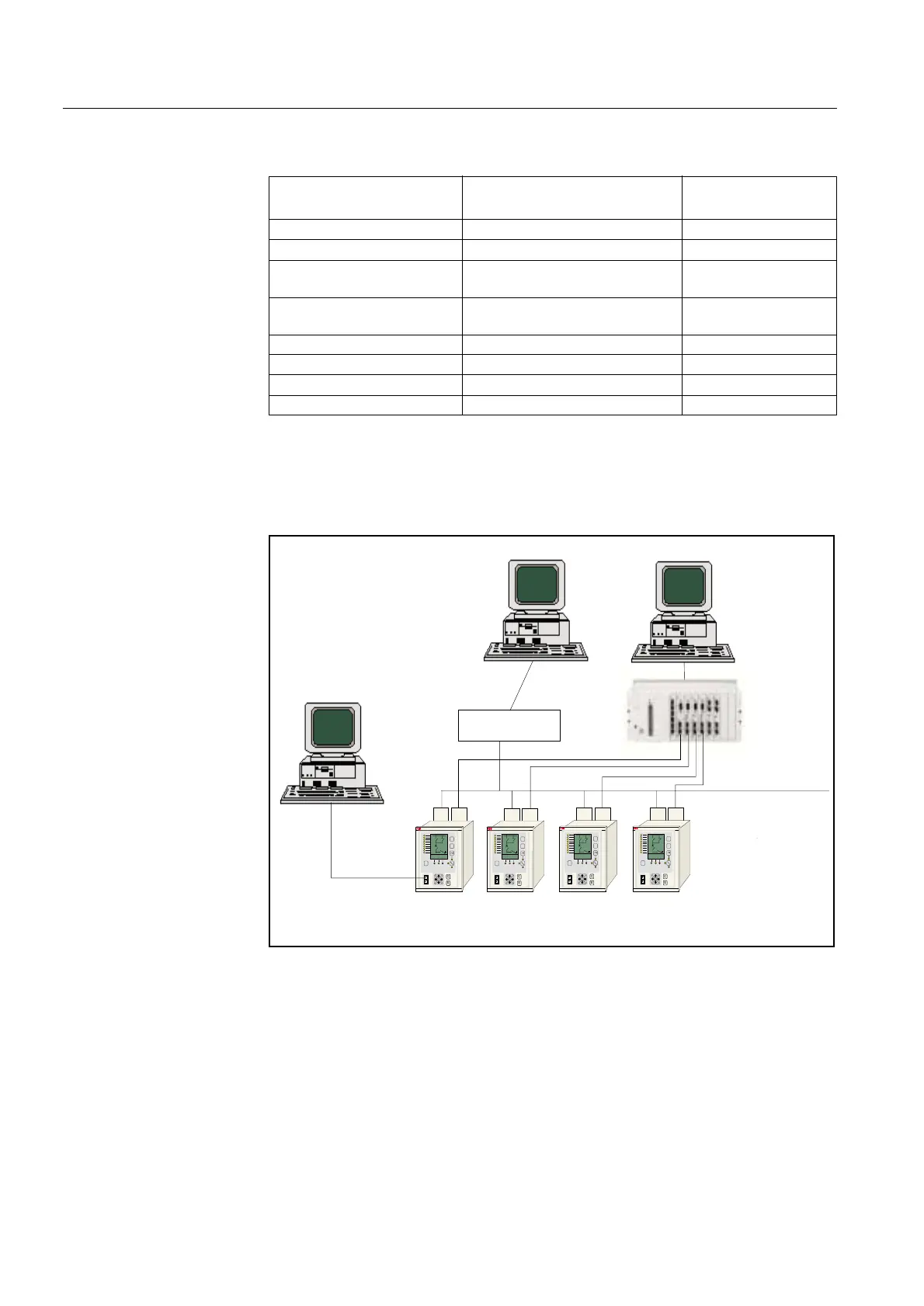
Other supported system configurations are represented in the following figures. A
LON bus and a parallel “SMS” bus connected as a SPA loop using the interface
module RER 123 on connector X3.2, allows to implement the redundant SMS
workstation.
)LJ /21DQG63$EDVHGVXEVWDWLRQDXWRPDWLRQV\VWHP
The REF 54_ feeder terminals connected with the IEC_103 to the IEC master device
using RER 123 on connector X3.2.
'DWDW\SH 5()!0LFUR6&$'$
5()DQG/6*
GHYLFHVWRHDFKRWKHU
Control commands transparent SPA bus messages -
Events and alarms sliding window protocol -
Status of breakers and
isolators
sliding window protocol network variables
Analogue measurement
values
sliding window protocol -
Other DI, AI data sliding window protocol network variables
Other DO, AO data transparent SPA bus messages network variables
Parameter data transparent SPA bus messages -
SPA file transfer data transparent SPA bus messages -
C
E
F
I
0
C
E
F
I
0
SMSbus2
C
E
F
I
0
C
E
F
I
0
SYS 500
COM 500
SMS 510
CAP 505
Protocol 2: SPA
Protocol 3: LON
SPA Fibre-optic
REF 54_ terminals connected
via the RER 103 to LON and via the RER 123 to SPA
SPA-ZC 22
LON Fibre-optic
RER 111 LON
star-coupler
CAP 501/505
SMS 510