Do you have a question about the ABB REX 521 and is the answer not in the manual?
Covers manual scope, copyright, trademarks, and general details.
Lists abbreviations and references to other technical documentation.
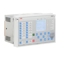
Introduces the Human-Machine Interface (HMI) components and features.
Explains the functionality of navigation, clear/cancel, and enter push-buttons.
Covers language selection and basic display adjustments like backlight and contrast.
Details password management, display contrast, and backlight behavior.
Describes how to perform a display test and select primary measurement values.
Information about the optically isolated serial communication port.
Presents the overall menu hierarchy and navigation structure of the relay.
Guides on accessing measurement data, event logs, and manual control operations.
Covers setting configuration parameters and modifying bit masks for events and switchgroups.
Explains protection indications, self-supervision, condition monitoring, and message priorities.
Details the meaning and behavior of Ready, Start, Trip, and Alarm LEDs.
Outlines the steps for testing digital inputs/outputs and internal relay faults (IRF).
Describes how to activate and test the Start and Trip outputs of function blocks.
| Product Type Designation | REX 521 |
|---|---|
| Current Input | 1 A or 5 A |
| Rated Control Supply Voltage (Us) | 24-250 V AC/DC |
| Communication Protocols | IEC 61850, Modbus |
| Protection functions | Overcurrent, Earth fault, Thermal overload, Under/over voltage, Frequency protection |
| Power supply | 24-250 V DC, 24-265 V AC |
| Enclosure | IP20 |