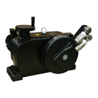
2 RHD250 to 4000 (Contrac) ELECTRICAL ROTARY ACTUATOR | SEI/RHD250/4000-EN REV. A
Table of contents
1 Safety .......................................................................... 3
General information and instructions .................................. 3
Warnings .................................................................................... 3
Intended use ............................................................................. 4
Improper use ............................................................................. 4
Notes on data safety ............................................................... 4
Warranty provisions ................................................................. 4
Manufacturer’s address .......................................................... 4
2 Introduction ............................................................... 5
Safety and precautions ........................................................... 5
Tools ........................................................................................... 5
3 Lubrication ................................................................. 6
Mounting position............................................................... 6
Oil change .................................................................................. 6
RHD oil types ........................................................................ 7
4 Maintenance ............................................................... 8
Safety instructions ................................................................... 8
General ....................................................................................... 8
Lever ........................................................................................... 8
Lever removal ............................................................................ 8
Lever installation ................................................................. 9
Ball-and-socket-joint .......................................................... 9
Tightening torques and dimensions of lever screws . 10
Sealing ring of output drive shaft ....................................... 11
Sealing ring of hand wheel drive / hand wheel shaft ...... 12
Sealing of the position sensor drive ................................... 12
RHD250...RHD800 ............................................................. 12
RHD1250... RHD4000 ............................................................. 13
Motor ........................................................................................ 13
Motor assignment and tightening torque .................... 13
Motor removal.................................................................... 14
Motor flange O-ring .......................................................... 14
Motor disassembly / assembly ...................................... 15
Exchange of motor bearings ........................................... 18
Exchange of motor shaft sealing ring ........................... 18
Brake adjustment ................................................................... 19
Brake of motor series 1 ......................................................... 19
Brake of motor series 2 ......................................................... 19
5 Electrical connections ............................................. 20
General ..................................................................................... 20
Covers ....................................................................................... 20
Electronic Unit EBN853 (Contrac) / EBN861 (Contrac) /
EBS862 (Contrac) ................................................................... 21
Analog / Digital .................................................................. 21
PROFIBUS DP®.................................................................... 22
Electronic Unit EBN852 (Contrac) ....................................... 23
Analog / Digital .................................................................. 23
Fuses ........................................................................................ 24
Electronic unit for field installation ............................... 24
Electronic units for rack installation ............................. 24
Fuse location EBN853 ...................................................... 25
Fuse location EBN861 / EBS862 ..................................... 25
External fuses for EBN861 / EBS862 ............................. 26
Fuse location in EBS852 ................................................... 26
6 Exchange of position sensor .................................. 27
Dismounting ........................................................................... 27
Mounting ................................................................................. 27
Mounting ................................................................................. 28
7 Electrical test values .............................................. 29
Test values (position sensor) .............................................. 29
Test values (Brake and Motor) ............................................ 30
Brake voltage ..................................................................... 30
Motor voltage .................................................................... 30
Winding resistance ........................................................... 30
8 Troubleshooting ...................................................... 31
LED signals at commissioning and service field ............... 31
9 Troubleshooting ...................................................... 31
General ..................................................................................... 32
Failures at brake, fuse or wiring ......................................... 33
Operation mode (MAN / AUT) ............................................. 34
Input configuration ............................................................... 35
Operation behind step controller ....................................... 36
Failure Diagram ...................................................................... 37
Failure due to response of positioning loop monitoring
38
General ..................................................................................... 38
User interface menus ............................................................ 39

 Loading...