Installation
42/68-165-EN RHD250 ... 4000 17
M00347
X
F
R
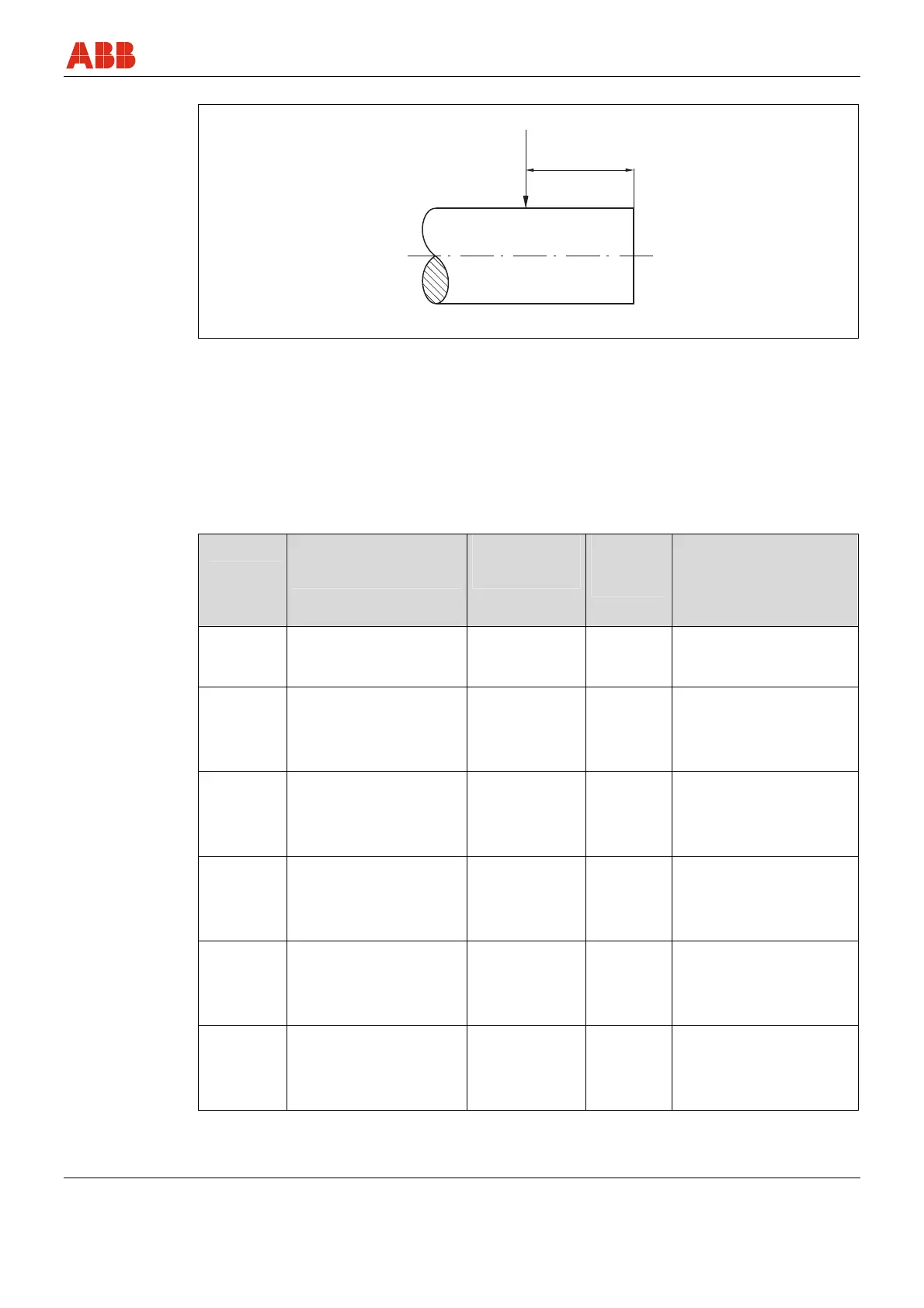
Fig. 5: Stub shaft
Configuring the drive element hub
The new drive element is mechanically connected to the drive shaft via a hole with feather key
groove . This connection must be constructed so that the rated torque and any possible output
torque is transmitted accurately. The drive element must be mounted securely on the drive shaft
with suitable measures to prevent axial shift. For the new drive element, you can use the current
mechanical stops.
The following parameters must be observed:
Type bore diameter
mm (inch)
Key width
mm (inch)
Hub
length
mm (inch)
Minimum yield strength
of hub Rp 0.2
N/mm
2
(pounds/square
inch)
RHD250
30 +0,033
(1.18 +0.0013)
8 -0,015/-0,051
(0.31 -0.0006/-
0.0020)
50 (1.97) 320 (46412.80)
RHD500
50 +0,039
(1.97 +0.0015)
14-0,018/-
0,061
(0.55 -0,0007/-
0.0024)
70 (2.76) 320 (46412.80)
RHD800
50 +0,039
(1.97 +0.0015)
14-0,018/-
0,061
(0.55 -0,0007/-
0.0024)
70 (2.76) 320 (46412.80)
RHD1250
70 +0,075/+0,030
(2.76 +0,0030/+0,0012)
20-0,022/-
0,074
(0.79 -0.0311/-
0.0029)
100 (3.94) 320 (46412.80)
RHD2500
70 +0,075/+0,030
(2.76 +0,0030/+0,0012)
20-0,022/-
0,074
(0.79 -0.0311/-
0.0029)
100 (3.94) 320 (46412.80)
RHD4000
85 +0,090/+0,036
(3.35 +0.0035/+0.0014)
25-0,018/-
0,061
(0.98 -0,0007/-
0.0024)
140 (5.51) 320 (46412.80)
Pos: 8.25 /====== = Seitenumbruch ======= = @ 0\mod_1126532365768_3101.doc @ 3830