Installation
42/68-167-EN RHDE250 ... 4000 (Contrac) 17
Pos: 11.22 /Montage/A ktorik/Elektr. S chwenkantriebe/RHDE250. ..4000/Montage mit Hebeltrieb @ 10\mod_11816 36578562_3101.doc @ 103649
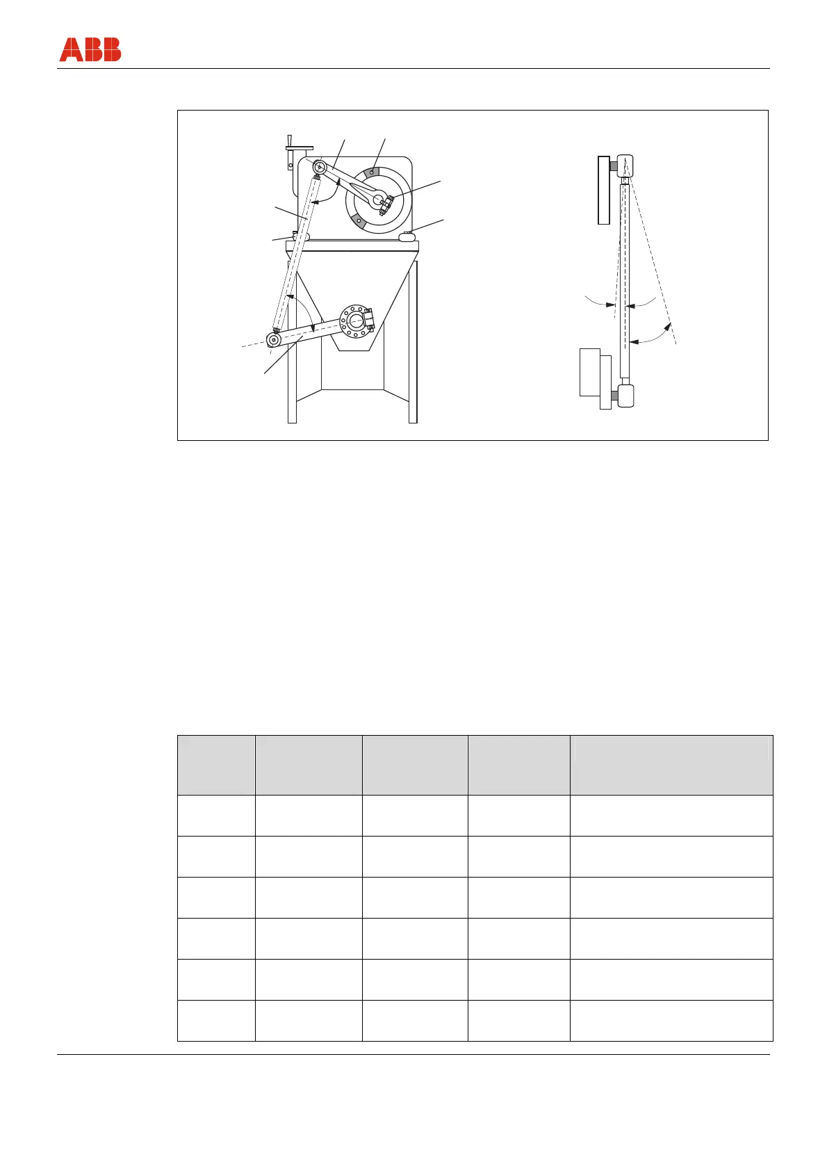
4.5.2 Mounting with lever
b
a
1
2
3
5
4
6
7
3°
10°
M00303
Fig. 4
1 Output lever
2 mech. limit stop with clamping screws
3 lever clamping screw
4 coupling tube
α ≥ 15° (≥ 20° for RHDE800 ... 4000)
5 Mounting screws
6 rigid, level support
7 Flap lever
β based on requirements of the valve
manufacturer
Pos: 11.23 /Montage/A ktorik/Elektr. S chwenkantriebe/RHDE250. ..4000/Montage mit a nderen Abtriebsele menten @ 12\mod_1189148136 281_3101.doc @ 121103
4.5.3 Installation with additional drive elements
When mounting an additional drive element instead of the standard lever, the following
installation conditions must be observed:
Max. perm. temperature of shaft:
Type radial force at
distance x
N (lbf)
Distance x
from shaft
edge mm (inch)
axial force
N (lbf)
max. output torque
RHDE250 1767 (397.24) 40 (1.57) 310 (69.69)
A short-term overload up to
double the rated torque is possible
RHDE500 7542 (1695.51) 35 (1.38) 1310 (294.50)
A short-term overload up to
double the rated torque is possible
RHDE800 7542 (1695.51) 35 (1.38) 1310 (294.50)
A short-term overload up to
double the rated torque is possible
RHDE1250 10100 (2270.57) 50 (1.97) 1750 (393.42)
A short-term overload up to
double the rated torque is possible
RHDE2500 10100 (2270.57) 50 (1.97) 1750 (393.42)
A short-term overload up to
double the rated torque is possible
RHDE4000 14142 (3179.25) 55 (2.17) 2455 (551.91)
A short-term overload up to
double the rated torque is possible