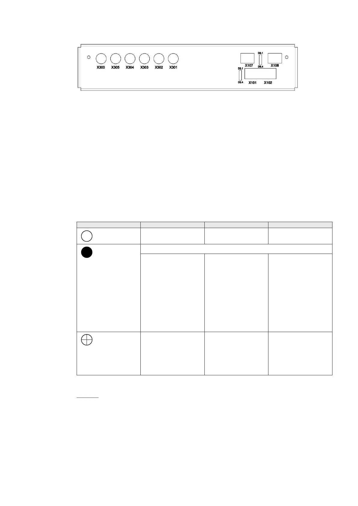
IEC18000533 V1 EN-US
Figure 24: TS side of the optical transceivers with the LEDs D2.1 to D2.4 and D9.1 to D9.4
7.2.3.1 Description of LED HMI functionality
GUID-C643D737-6D44-44C9-818F-EB73C4CA49E4 v1
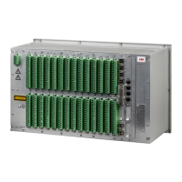
On the top-plate of each SAM600 module, there are three status LEDs which have a fixed
function and cannot be configured.
The function of each LED is as follows:
• The green LED (READY) indicates the operation status of a SAM600 module.
• The yellow LED (WARNING) indicates any warning caused by an issue related to a SAM600
module.
• The red LED (ALARM) indicates severe hardware failure or software malfunction of the
SAM600 module.
Table 12: LED status
Function Green LED (Ready) Yellow LED (Warning) Red LED (Alarm)
= No indication
Power down No warning No alarm
= Steady light
Module is in Bootloader (all LEDs steady light)
Module is operating
normally with a valid
configuration
• Module is missing a
sample stream for
merging
• Module’s board
temperature
exceeds threshold
• Module A/D
calibration integrity
check failed
• SAM600 system
bus single link
failure
• Communication
error in the SAM600
module chain
• Module’s digital
input HW error
• Module software
failure
• SAM600 application
disabled
• SAM600 system
bus double link
failure
= Flash
• Module is starting
up
• Module operates
normally and waits
to receive a
configuration
Simulation mode
activated
Module’s time
synchronization is not as
configured
Table 13 lists the LED HMI definitions applicable optical transceiver states.
1MRK 511 434-UEN B Section 7
Technical Data
SAM600 Process Bus I/O System 47
Operation Manual
© Copyright 2017 ABB. All rights reserved