4
Block diagram
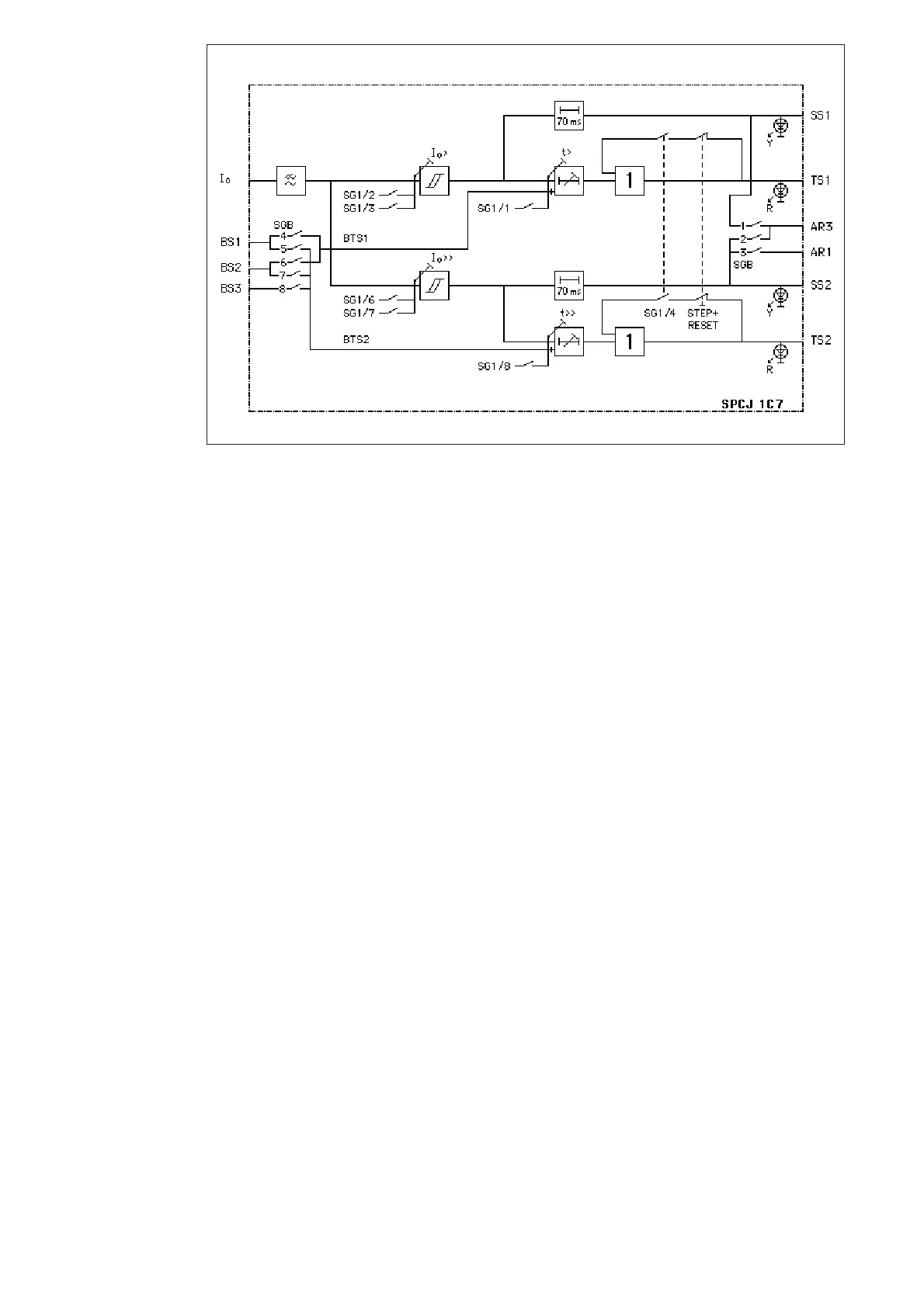
Fig. 2. Block diagram for the sensitive residual overcurrent relay module SPCJ 1C7
I
0
Energizing current (neutral current or residual current)
BS1, BS2, BS3 External blocking signals
BTS1 Blocking of the operation of stage I
0
>
BTS2 Blocking of the operation of stage I
0
>>
SG1 Selector switchgroup on the front panel
SG2 Indicator operation mode selector switchgroup (not shown in figure)
SGB Selector switchgroup on the PC board for blocking signals and for the starting
signals for auto-reclose functions, if applicable
SS1 Start signal of stage I
0
>
TS1 Operate signal of stage I
0
>
SS2 Start signal of stage I
0
>>
TS2 Operate signal of stage I
0
>>
AR1, AR3 Start initiation signals for auto-reclosure functions
I
0
> Start current setting of the low-set stage I
0
>
I
0
>> Start current setting of the high-set stage I
0
>>
t> Operate time setting of the low-set stage I
0
>
t>> Operate time setting of the high-set stage I
0
>>
Y Yellow indicator, starting
R Red indicator, operation
NOTE!
All input and output signals of the relay module
are not necessarily wired to the terminals of
every protection relay using this module. The
signals wired to the terminals are shown in the
diagram illustrating the signal interchange be-
tween the relay modules of the protection relay
or feeder terminal in question.
 Loading...