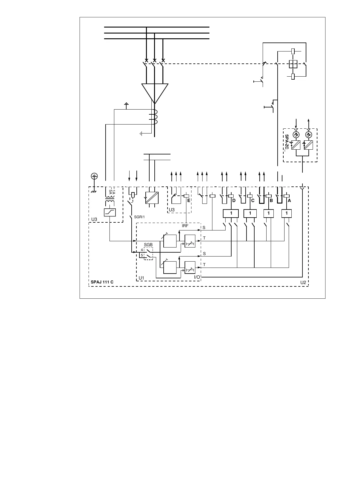
4
L1
L2
L3
0
I
0
I
-
-
+
+
BS
5A
1A
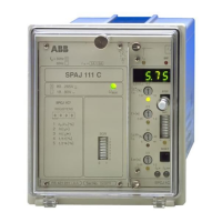
SPAJ 111 C
U2
U3
1111
DCBA
+
U
25
SGR/1
U3+-
E
+
-
(~)
(~)
≅
_
10 11 61 62 71 7270 7877 8180 6968 6665
SGR 7 5 683 2 4
START1 SIGNAL1 TRIP2 TRIP1
SPA-ZC_
Rx Tx
26 27
IRF
IRF
747573
F
START2
TS2
TS1
SGB
SS1
SS2
U1
5
4
I/O
t >>
t >
Io>
Io>>
SERIAL
PORT
aux
Fig. 2. Connection diagram for the sensitive earth-fault relay SPAJ 111 C.
U
aux
Auxiliary voltage
A,B,C,D,E,F Output relays
IRF Self-supervision function
BS Blocking signal
SS Start signal
TS Trip signal
SGR Switchgroup for configuring trip and alarm signals
SGB Switchgroup for configuring blocking signals
TRIP_ Trip output
SIGNAL1 Signal on relay operation
START_ Start signal or signal on relay operation
U1 Sensitive earth-fault relay module SPCJ 1C7
U2 Power supply and I/O module SPTU 240S1 or SPTU 48S1
U3 I/O module SPTE 1E12
SERIAL PORT Serial communication port
SPA-ZC_ Bus connection module
Rx/Tx Receiver (Rx) and transmitter (Tx) of the bus connection module
Connections