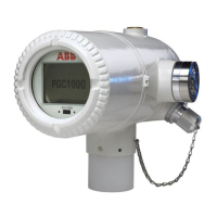
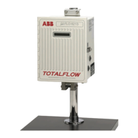
The ABB Totalflow XFC/XRC Series is a line of flow computers and remote controllers primarily designed for gas orifice applications. These devices are crucial for accurate measurement and control in various industrial settings, offering robust features for installation, setup, and communication.
Function Description:
The XFC (flow computer) and XRC (remote controller) series units are designed to measure and control gas flow. The XFC specifically handles flow computation, while the XRC focuses on remote control functionalities. Both units are equipped to interface with various sensors and communication systems to provide comprehensive data acquisition and control. The XFC measures flowing gas temperature using an RTD probe, a feature not available on the XRC. The devices calculate total accumulated volume, current flow rate, differential pressure, static pressure, and flowing temperature, among other parameters. They also track battery voltage and charger voltage, providing critical operational status.
Important Technical Specifications:
- RTD Inputs: The XFC board includes RTD inputs (J7 connector block) for temperature measurement, while the XRC board does not.
- Memory Backup: Both XFC (J13) and XRC (J1) boards have a jumper setting to enable memory backup.
- Battery Connection: Main battery packs connect to J1 on XFCs and J16 on XRCs.
- Charger Input: Solar panel or AC charger inputs connect to J5 on XFCs and J17 on XRCs.
- Communication Ports: Both XFC and XRC units feature remote communication ports that can function as RS232, RS485, or RS422, depending on the configuration. The XFC has one Switched V-Batt/Operate line, which should be enabled on only one Comm Port if needed.
- Display: The units feature an LCD display that scrolls through default display items, including date/time, various pressure and temperature readings, flow rates, volumes, and battery status.
- Annunciators: The display includes annunciators (A1-A8) for visual alarms and status codes, indicating conditions such as low lithium battery, low charger voltage, communication status (transmitting, receiving, waiting for acknowledgment, ID recognized), and various measurement application statuses (back flow, zero flow, hold, alarm, A to D failure).
- Protocols: Supports Totalflow Remote protocol, Modbus ASCII, Modbus RTU, Local Protocol (PCCU32), Packet Protocol, and LevelMaster Protocol.
- Software Compatibility: Requires PCCU32 software Version 4.3 or higher and FS/2 (if used) Version 2018583-007 or higher for setup and calibration.
Usage Features:
- Physical Mounting: Supports various mounting options including saddle mount (U-bolts to 2" pipe), pipe mount (U-bolts to 2" mounting pipe), and direct manifold mount. Proper manifold mounting is crucial for accurate flow direction (left to right or right to left) based on the AMU model number.
- Piping: Requires stainless steel tubing from the manifold to orifice tap valves. Recommendations include large bore, short, equal length gage lines with a downward slope to taps (at least 1" per 3 feet) for best measurement.
- RTD Probe Installation: The RTD probe is installed into the meter run using a thermowell and wired to the J7 connector block on the XFC board. The probe length is adjustable to be spring-loaded against the bottom of the thermowell.
- Battery Installation: Prior to installation, fully charge the battery pack to extend its life. The battery pack is inserted into the compartment, and its connector is attached to the main electronics board.
- Solar Panel Installation: Solar panels can be assembled, mounted, and connected to the unit's charger input terminals. Proper orientation (south in northern hemisphere, north in southern hemisphere) and secure tightening of U-bolts are essential. A "dip" in the cable is recommended to prevent moisture entry.
- Setup via PCCU32/FS/2: The unit can be connected to an FS/2 or a laptop running PCCU32 for initial setup. This includes setting date/time, ID, location, AGA setup, and verifying/calibrating static pressure, differential pressure, and temperature.
- Calibration Mode: Allows for verification and calibration of pressure and temperature registers. Users can select "RTD Installed," un-check "Use Fixed TF," and adjust RTD Bias. "As found" and "as left" calibration checks are performed in this mode.
- On-Line Operation: After calibration, the unit is placed on line by carefully opening orifice tap valves and closing bypass valves. Volume calculation can be verified via the display or PCCU32.
- Data Collection: Event and characteristic files can be reviewed to ensure all parameters are set properly.
- Reset Volume Command: An optional command in PCCU32 to establish an official starting point for live data, recorded in the Events file.
- Display Customization: The duration each parameter is displayed can be varied from 1 to 255 seconds, or turned off by setting it to 0 seconds.
Maintenance Features:
- Troubleshooting: A comprehensive checklist is provided for communications troubleshooting, covering issues like protocol selection, communication module integrity, battery voltage, ID matching, baud rate, security code, link establishment time, packet protocol usage, and wiring.
- Wiring Checks: A multimeter can be used to check for wiring shorts or opens by testing continuity (resistance) between wires.
- Battery Management: Recommendations for recharging batteries include quick charges to remove buildup, which is more effective than trickle charges for battery recovery. Storing batteries in a cool environment helps reduce drainage.
- Lithium Battery Monitoring: The unit displays a "low lithium alarm" (ㄴ) if the lithium battery voltage drops below 2.5 volts, indicating it needs replacement.
- Startup Diagnostics: The unit performs a startup routine, displaying boot/loader PROM information, verifying flash, and checking checksums. If the display does not scroll, troubleshooting steps include power cycling and using the "0.0.0=COLD" command in PCCU32's Terminal Mode to initiate a cold start.
- Alarm and Status Codes: The LCD displays various alarm and status codes (e.g., low lithium battery, low charger, communication status, measurement conditions) to alert users to operational issues. These annunciator assignments can be verified and managed via PCCU32.