Easy parts replacement in the
most accurate and reliable single
run gas flow computer
Introduction
This guide is designed for typical installations only. Maintenance must be performed
by personnel knowledgeable of the ABB Totalflow
®
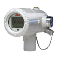
µFLO
G5
flow computer, the
integral multivariable transducer (IMV), and the theory of natural gas electronic flow
measurement. Maintenance personnel must also be knowledgeable of local and
national codes as they apply to hazardous areas, communication wiring, and
electrical wiring.
Read and consider the contents of this guide prior to beginning installation of the
equipment. If for some reason there are questions that are not answered in this
guide, or other documentation listed in the following section, call the local ABB
representative, or call the main office number listed on the back page of this guide.
CAUTION – Equipment damage. The µFLO
G5
flow computer operating
temperature range differs from the µFLO
G4
. The µFLO
G5
is rated for
ambient temperatures between -40 °F and +158 °F (-40 °C and +70 °C).
Purpose
This guide provides easy-to-follow instructions for replacement of all available spare
part components.
Application guide
G5 flow computers
µFLO
G5
(microFLO
G5
)
Component replacement instructions