2105514-001 rev. AB | 7
J12
DO
+
-
DI
1
2
COMMUNICATIONS
+
-
1
2
J13
J10
S1
J8
J5
J2
J9
DI
DO
3
1
J7
3
1
J10
3
1
J6
J6/J10 CFG
1-2
2-3
0-20 mA
0-10 V
AI2
J4
AI1
WHEN OPERATING IN
RS-232 MODE
S1: 1 & 2 MUST
BE S ET T O O FF
RS485/TBUS
RBUS
Bus
Ter min at io n
ON
Communicati ons
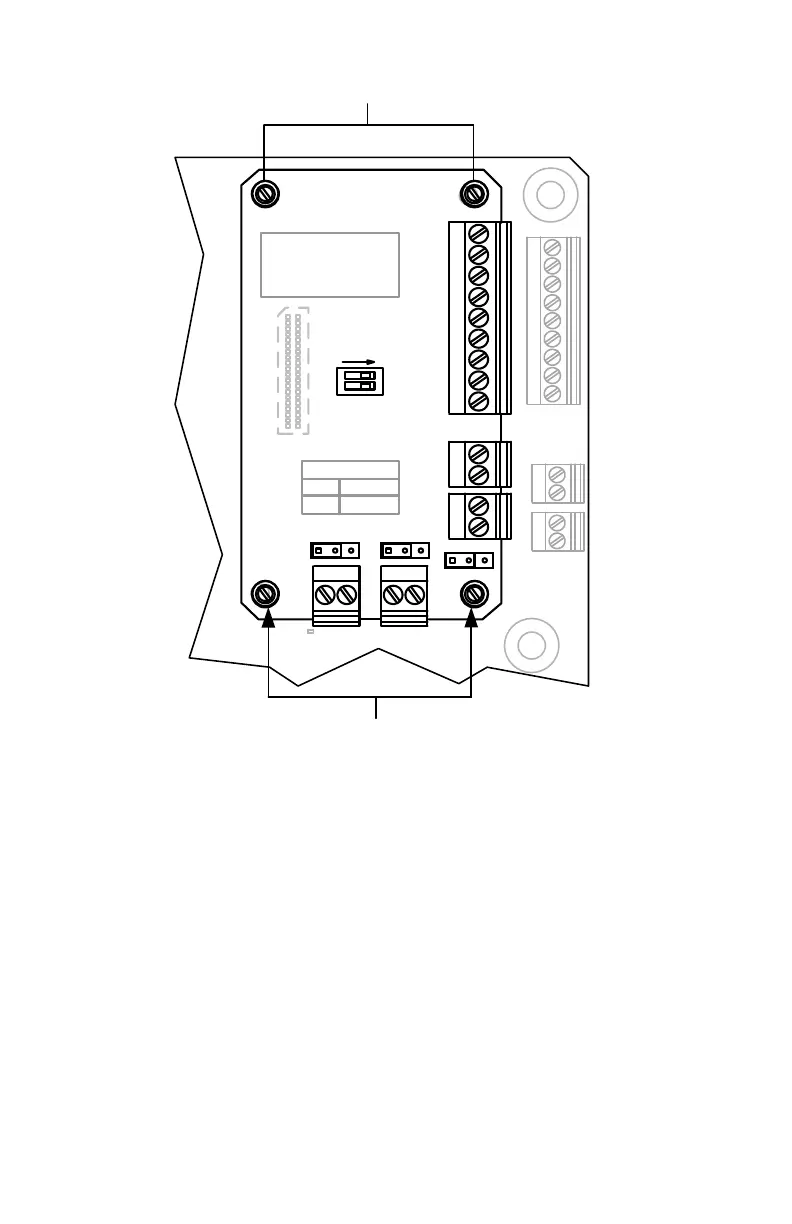
Expansion board
mounting screws
Expa nsi on board
mounting screws
Figure 2: µFLO
G5
I/O expansion board
4. Use a small slotted screwdriver to loosen the four (4) mounting screws that
attach the I/O board to the µFLO
G5
board. Alternate between the four screws,
one to two turns each. As the screws are loosened, the J2 connector is
gradually disconnected from the electronic board socket. The mounting screws
are held in place with a screw keeper.
5. Grasp the expansion board on either side and gently lift up from the µFLO
G5
electronic board.
If only replacing the I/O expansion board, continue to section 3.4.2, Reinstall the I/O
expansion board, on page 8. Otherwise, set the board aside to reinstall at a later
time.
 Loading...