10 | 2105514-001 rev. AB
3.5 Replacing the µFLO
G5
electronic board
3.5.1 Remove the electronic board
This procedure is applicable only for the direct replacement of the µFLO
G5
electronic
board. If removal of the electronic board is required during another procedure, those
instructions will be addressed in that procedure.
To remove the µFLO
G5
electronic board:
1. Follow the procedure in section 3.1, Preserving data and configuration files, on
page 5. Return here when completed.
2. Follow the procedure in section 3.2, Disconnect power, on page 5. Return here
when completed.
3. Follow the procedure in section 3.4.1, Remove the I/O expansion board, on
page6. Return here when completed.
4. Disconnect the following, if connected, from the µFLO
G5
electronic board:
a. LCD display cable from J8 connector.
b. Communication connections:
- MMI communication cable plug from J9
- USB cable plug from J4
- Ethernet cable plug from J1
c. Field wiring connections:
- Communication wiring from J10
- DI wiring from J12
- DO wiring from J13
- RTD sensor from J3
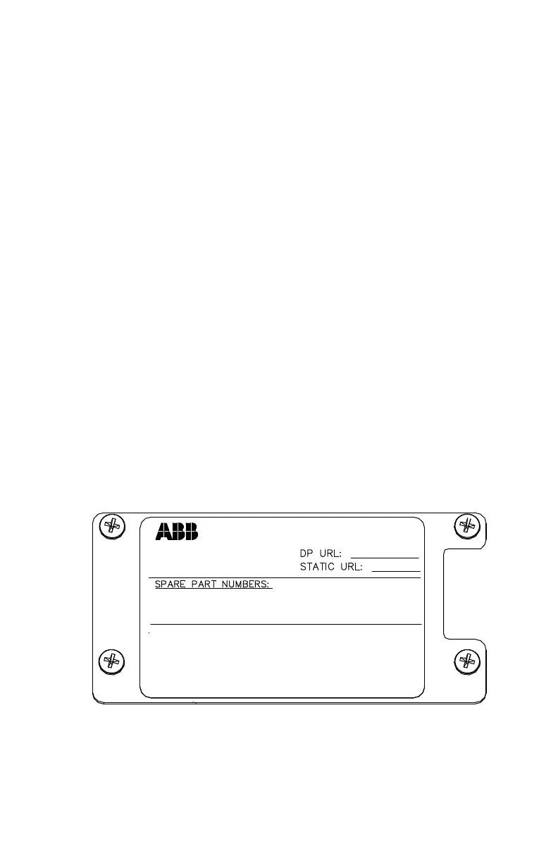
5. On the transducer housing assembly, use a phillips screwdriver to remove the
four (4) screws that attach the cover plate that contains the transducer
information. Remove and set the plate aside (Figure 4). The cover plate should
always stay with the IMV.
Static pressure sensor is on the
upstream (+ side) of DP sensor.
MADE IN U.S.A.
TOTALFLOW Products
Set f low computer SP tap
location to upstream.
2105263- __
IMV COMPLETE:
2104 600-009
PROCESS WETTED MATERIALS OF TRANSDUCERS CONFORM TO NACE MR-01-75
SENSOR ONLY (LOL NOTCRE): 2104797-0XX
SENSOR W/CONTROLLER BOARD INSTALLED: 21052634-5XX
CONTROLLER BOARD : 2104939-001
IN H2O
PSIA
Figure 4: Cover plate with transducer information
6. Using a ¼ inch hex driver, remove the six (6) hex standoffs that attach the
µFLO
G5
electronic board to the transducer housing.
 Loading...