8 | 2105514-001 rev. AB
3.4.2 Reinstall the I/O expansion board
WARNING – Bodily injury and property damage. Wiring peripheral
devices to the flow computer electronic board should be performed
prior to applying power. Do not apply power until instructed to do so.
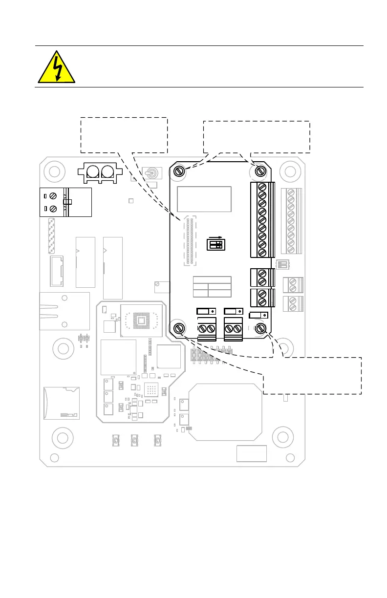
1. Fit the I/O expansion board connector (J1) onto the expansion port (J2) on the
electronic board, but do not push down to seat the expansion board.
Figure 3: µFLO
G5
Board – J2 Connector
2. Using a small slotted screwdriver, begin turning each captive screw a few turns
each, moving sequentially to each of the 4 (four) corners of the board, to slowly
seat the board into the onboard connector. Continue until the board is fully
seated.
1
18
A
V
1
2
3
7
8
9
AB
CD
E
F
G
HJ
K
V
V
I
I
V
V
I
I
V
V
I
I
J7
987654321
S1
J6
14
13
12
11
10
9
8
7
6
5
4
3
2
1
J11
6
5
4
3
2
1
S2
S5
S4
J16
J4
J9
J12
J8
J1
BA RCODE
TAG
DO
+
-
DI
1
2
RESET
WA RM
WA KE
RESET
COLD
SHL D
(OUT)
(IN)
(-)
(+)
uSD
ACTI VITY
LINK
ETH E RNE T
DISPLAY
MMI
USB
RESET
OFF
ON
SECURITY
R12
COMMUNICATIONS
S3
O
N
+
-
1
2
J13
J10
J3
RTD
1
2
1
2
3
S1
J8
J5
J2
J9
DI
DO
3
1
J7
3
1
J10
3
1
J6
J6/J10 CFG
1-2
2-3
0-20 mA
0-10 V
AI2
J4
AI1
WHEN OPERATING IN
RS-232 MODE
S1: 1 & 2 MUST
BE SET TO O FF
RS485/TBUS
RBUS Termination
ON
Fit the I/O card connector J1
into J2 on the board. Do not
push down to seat.
Gradually tighten the screws, 2-3 half-
turns at a ti me. Take turns,
sequentially, around the board until the
boar d is s ecure and the conne ctor i s
properly seated.
The (4) captive screws at the corners
must be used together to work the boa rd
into its correct position.
J17
CHRG/
EXT
POWER
J15
12 V SLA BAT
 Loading...