Operation Manual / TPL67-C.. - TPL71-C..
Removing the turbocharger
Page 86
© Copyright 2017 ABB. All rights reserved.
February 2017 HZTL2488_EN Revision D
Removing the turbocharger
7.2
Disconnect all gas, air and oil lines in accordance with engine manu-
facturer’s instructions.
An orifice plate for adjusting the oil pressure is fitted in each of the two
oil inlet channels in the bearing casing. When the cartridge group, the
bearing casing or the turbocharger is fitted to the engine, it must be en-
sured that the orifice plates that are specified for the turbocharger have
been installed in the two oil inlet channels.
Check correct installation of oil orifice plates.
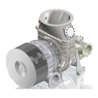
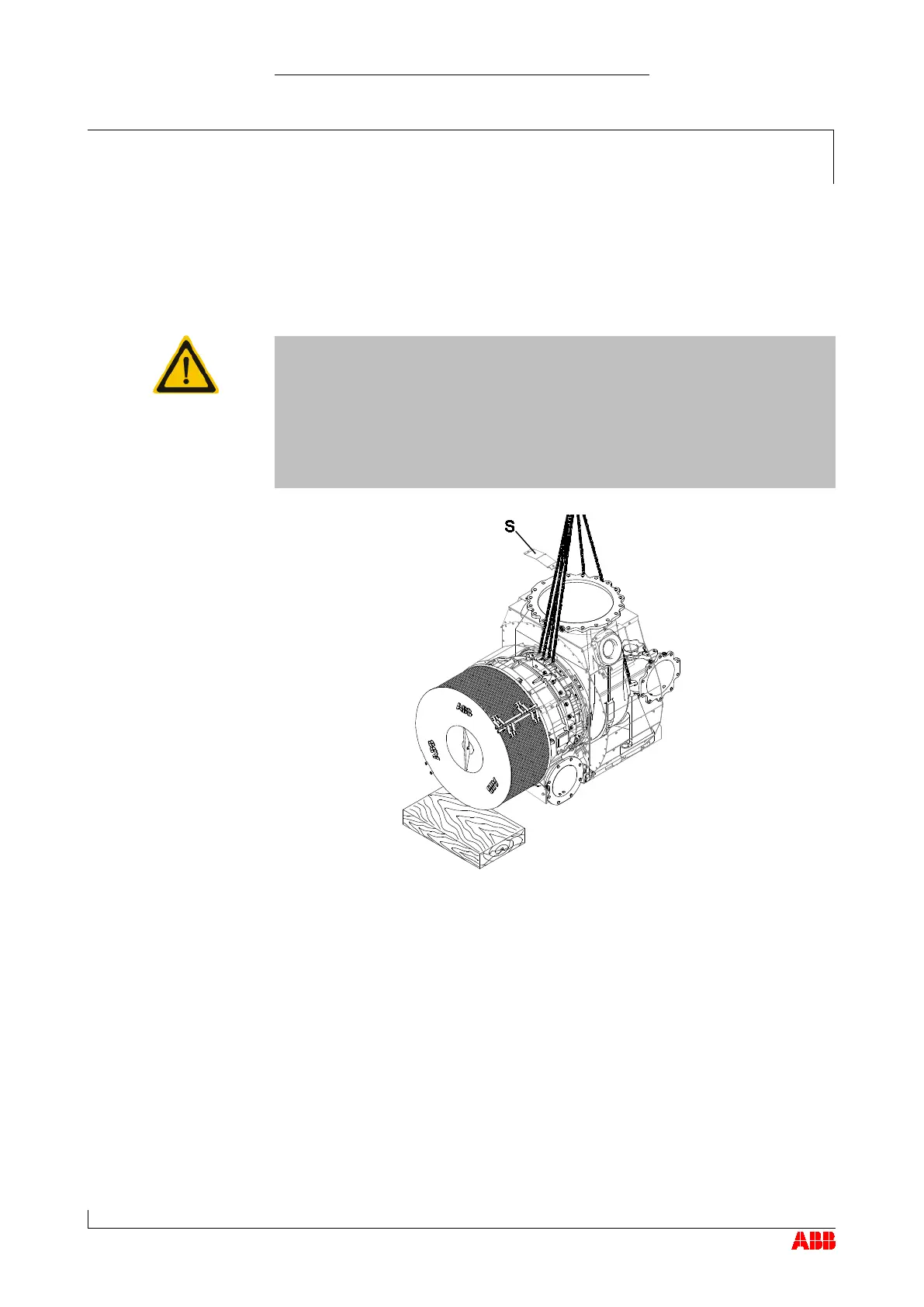
Use the two suspension eyes on the bearing casing (observe the marking
on the insulation). The lifting gear around the gas inlet casing serves to
align the turbocharger horizontally.
Remove the insulation shell (
) from the bearing casing and possibly
the insulation on the gas inlet casing. Leave any remaining insulation
on the turbocharger.
Version with compressor wheel cooling system
Remove air supply line. (See also chapter entitled Preliminary remarks /
Layout and functionality)
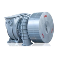
Inspect the lifting gear.
Attach one lifting gear each to the two ribs of the bearing casing pro-
vided for this purpose.
 Loading...