7
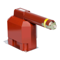
Capacitive voltage indicator (divider)
The transformer can be supplied with the capaci-
tive voltage indicator on the request. Integrated
voltage detection system is corresponding to Sep-
arable Voltage Detection System according to IEC
61234-5. It is integrated coupling electrode con-
nected to secondary terminal (terminal Ck). Elec-
trode acts as a capacitor between electrode and
primary winding (C1), or electrode and ground
(C2). If the electrode is connected to an indication
device (not part of delivery – it is part of switch-
gear) it works as indication of voltage presence –
more in IEC 61234-5.
Ub (kV)
Tab. 3. CE capacity according to nominal voltage
Note: Recommended min. capacities for nominal
voltage.
The fuse can be a part of a supply of voltage trans-
formers with a fuse. We can supply following
fuses:
Rated
current (A)
Rated voltage
(kV)
(mm)
Striker pin
(*) Available only for certain types
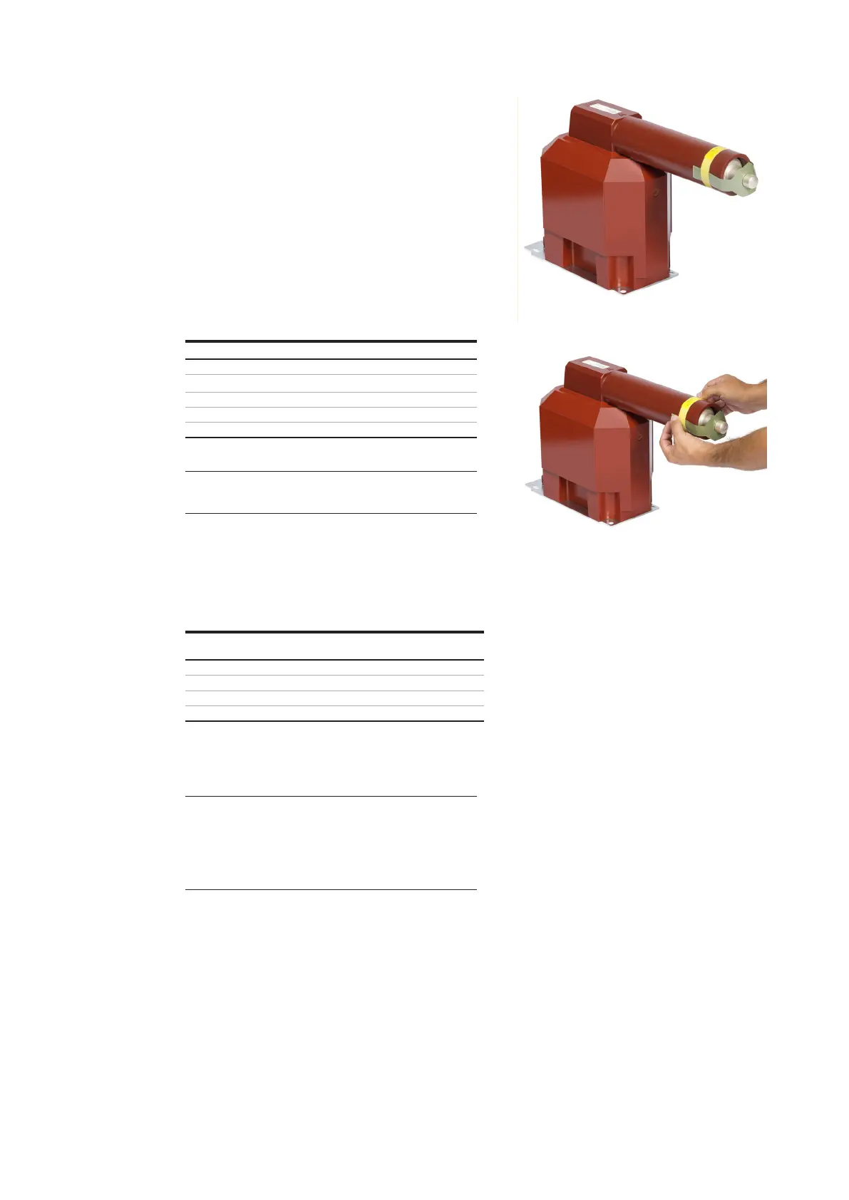
Warning: The majority of VT types TJP/TJPH
have a fuse contact equipped with a fixation for
transportation. If this fixation is present, it
must be removed before VT’s installation. See
tential) transformers fuse replacement
External fuse holder
the external fuse holder and It can be installed in
sories are a part of delivery and shall be used for
mum allowed torque for screw connection is 20
4. Instructions for use
Current and voltage instrument transformers are
used:
• to convert large currents or voltage in the pri
mary circuit to an appropriate level for second
• to insulate primary and secondary circuit from
each other to protect the secondary equipment
from the harmful effects of large current or volt
age appearing during the operation (short cir
The use of current or voltage transformer for
other purpose than described above is forbidden
—
10 Delivered VT
with fixation
—
—
10
—
11