TTR200 | OI/TTR200-EN Rev. B 5
2 Use in potentially explosive
atmospheres according to ATEX and
IECEx
NOTICE
— Further information on the approval of devices for use in
potentially explosive atmospheres can be found in the
explosion protection test certificates (at
www.abb.com/temperature).
— Depending on the design, a specific marking in
accordance with ATEX or IECEx applies.
2.1 Ex-marking
ATEX intrinsic safety
The device fulfills the requirements of Directive 2014/34/EU in
case of corresponding purchase orders and is approved for
use in Zone 0, 1 and 2.
Model TTR200-E1
Type Examination Test Certificate: PTB 05 ATEX 2017 X
II 1 G Ex ia IIC T6 Ga
II 2 (1) G Ex [ia] ib IIC T6 Gb (Ga)
II 2 G (1D) Ex [iaD] ib IIC T6 Gb (Da)
ATEX Non-sparking
The device fulfills the requirements of Directive 2014/34/EU in
case of corresponding purchase orders and is approved for
use in Zone 2.
Model TTR200-E2
Declaration of conformity
II 3 G Ex nA IIC T1-T6 Gc
IECEx intrinsic safety
Approved for use in Zone 0, 1, and 2.
Model TTR200-H1
IECEx certificate of conformity IECEx PTB 09.0014X
Ex ia IIC T6...T1 Ga
Ex [ia] ib IIC T6...T1 Gb (Ga)
Ex [ia IIIC Da] ib IIC T6...T1 Gb
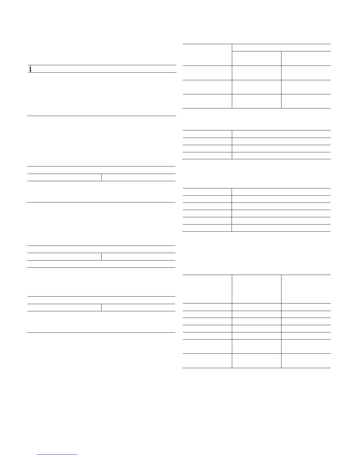
2.2 Temperature data
ATEX / IECEx intrinsic safety
Temperature class Permissible ambient temperature range
Device category 1
use
Device category 2 / 3
use
T6 -40 … 44 °C
(-40 ... 111.2 °F)
-40 … 56 °C
(-40 ... 132.8 °F)
T5 -40 … 56 °C
(-40 ... 132.8 °F)
-40 … 71 °C
(-40 ... 159.8 °F)
T4-T1 -40 … 60 °C
(-40 ... 140.0 °F)
-40 … 85 °C
(-40 ... 185.0 °F)
ATEX Non-sparking
Temperature class Device category 3 use
T6 -40 … 56 °C (-40 ... 132.8 °F)
T5 -40 … 71 °C (-40 ... 159.8 °F)
T4 -40 … 85 °C (-40 ... 185.0 °F)
2.3 Electrical data
Intrinsic safety type of protection Ex ia IIC (part 1)
Supply circuit
Max. voltage U
i
= 30 V
Short-circuit current I
i
= 130 mA
Max. power P
i
= 0.8 W
Internal inductance L
i
= 160 µH
1)
Internal capacitance C
i
= 0.57 nF
2)
1) From HW rev. 1.12, previously L
i
= 0.5 mH.
2) From HW rev. 1.07, previously C
i
= 5nF.
Intrinsic safety type of protection Ex ia IIC (part 2)
Thermocouples, voltages
Measurement circuit:
resistance
thermometer,
resistances
Measurement circuit:
thermocouples,
voltages
Max. voltage U
o
= 6.5 V U
o
= 1.2 V
Short-circuit current I
o
= 17.8 mA
1)
I
o
= 50 mA
Max. power P
o
= 29 mW
2)
P
o
= 60 mW
Internal inductance L
i
= 0 mH L
i
= 0 mH
Internal capacitance C
i
= 118 nF
3)
C
i
= 118 nF
3)
Maximum permissible
external inductance
L
o
= 5 mH L
o
= 5 mH
Maximum permissible
external capacitance
C
o
= 1.55 F C
o
= 1.05 F
1) From HW rev. 1.12, previously I
o
= 25 mA.
2) From HW rev. 1.12, previously P
o
= 38 mW.
3) From HW rev. 1.12, previously C
i
= 49 nF.
 Loading...


