TTR200 | OI/TTR200-EN Rev. B 7
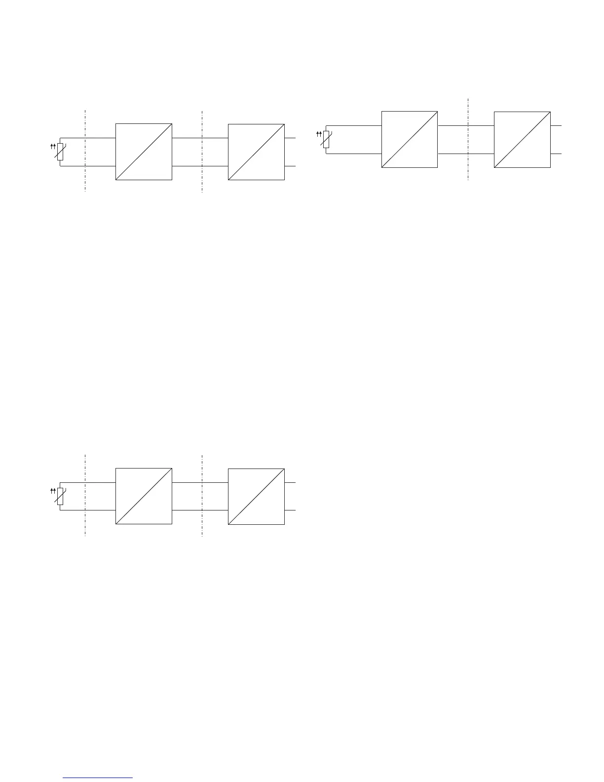
ATEX - Zone 1 (0)
Marking: II 2 (1) G Ex [ia] ib IIC T6 Gb (Ga)
Zone 0
or 1
Ex area Zone 1 Safe area
Fig. 3
A Sensor B Transmitter in the housing with IP rating IP 20
C Supply isolator [Ex ib]
When used in zone 1, the input for the supply isolator must be
in [Ex ia] design.
When using the transmitter in Zone 1, you must ensure that
impermissible electrostatic charging of the temperature
transmitter is prevented (observe the warnings on the device).
As the user, it is your responsibility to ensure that the sensor
instrumentation meets the requirements of applicable
explosion protection standards. The sensor can be installed in
Zone 1 or Zone 0.
ATEX - Zone 1 (20)
Marking: II 2 G (1D) Ex [iaD] ib IIC T6 Gb (Da)
Zone 0, 1
or 20
Ex area Zone 1 Safe area
Fig. 4
A Sensor B Transmitter in the housing with IP rating IP 20
C Supply isolator [Ex ib]
When used in zone 1, the input for the supply isolator must be
in [Ex ia] design.
When using the transmitter in Zone 1, you must ensure that
impermissible electrostatic charging of the temperature
transmitter is prevented (observe the warnings on the device).
As the user, it is your responsibility to ensure that the sensor
instrumentation meets the requirements of applicable
explosion protection standards. The sensor can be installed in
Zone 0, Zone 1, or Zone 20.
ATEX - Zone 2
Marking: II 3 G Ex nA IIC T1-T6 Gc
Ex area Zone 2 Safe area
Fig. 5
A Sensor B Transmitter in the housing with IP rating IP 54
C Supply isolator
When using the transmitter in Zone 2, observe the following:
— The temperature transmitter must be installed in its own
housing. This housing must at least meet IP rating IP54 (in
accordance with EN 60529) and the other requirements of
the potentially explosive atmosphere (e. g. a certified
housing).
— External measures must be made for the power supply
circuit in order to prevent the rated voltage from being
overshot by more than 40% in the event of transient
disturbances.
— The electrical connections may only be opened or closed
when there is no hazardous atmosphere.
— When using the transmitter in Zone 2, you must ensure
that impermissible electrostatic charging of the
temperature transmitter is prevented (observe the
warnings on the device).
2.5 Commissioning
The commissioning and parameterization of the device may
also be carried out in potentially explosive atmospheres using
a handheld terminal that has been approved accordingly under
consideration of an intrinsic safety installation check.
Alternatively, an Ex modem can be connected to the circuit
outside the potentially explosive atmosphere.
2.6 Operating instructions
2.6.1 Protection against electrostatic discharges
The plastic parts inside the device can store electrostatic
charges.
Make sure that no electrostatic charges can accumulate when
handling the device.
A10209
ib
ia
J
ACB
A10210
ib
ia
J
ACB
ib
A10211
J
ACB
 Loading...


