1ZSE 5492-124 en, Rev. 6 | Maintenance guide UCG 11
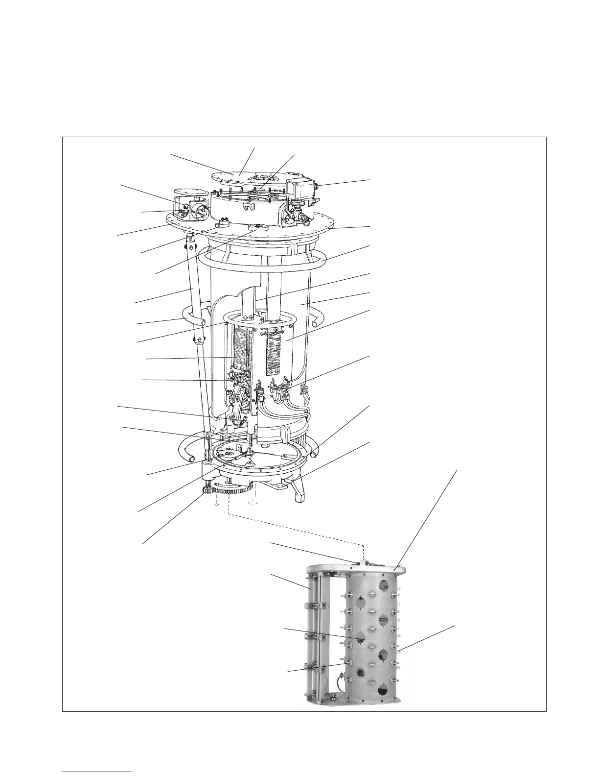
Fig. 2. General arrangement of on-load tap-changer, type UC.
Bottom valve for
drying process
Pressure relay
Top-section
Shielding-ring
1)
Diverter switch
Plug-in contacts
Bottom section
Oil valve
Cover
Driving disc for the
diverter switch
Insulating cylinder
Draining tube
Guide-pins
Current terminal
Transition resistors
Fixed and moving
contacts
Intermediate gear
Insulating shaft
Bevel gear
Position indicator
Earthing terminal
Serial No.
Diverter switch housing
Serial No.
Connection ange for
gas operated relay
Shielding-ring
2)
Shielding-ring
1)
1) Only at impulse withstand voltage
to earth of 650 kV and 1050 kV.
2) Not on UCG of the short type.
Tap selector
Moving ne-
selector contacts
Change-over
selector
Geneva gear
Current collector
Fixed ne-selector
contacts

 Loading...


