18
—
4. Panel design and equipment
Circuit-breaker compartment
The circuit-breaker compartment contains all the
necessary equipment for reciprocal operation of
the withdrawable part and the panel. Like the
busbar compartment, it is metallically partitioned
on all sides.
The tulip isolating contacts together with the
fixed isolating contacts are located in mounting
plate. The metal shutters covering the insertion
openings are also included. The shutters are
opened by the actuating bars of the withdrawable
circuit-breaker part, using the lever when
inserting into the service position and are closed
when the apparatus is removed. In the test /
disconnected position of the withdrawable part
partitioning by separation is established in the
main current circuit. Connection of the control
wiring required for test purposes needs not be
interrupted when in the test / disconnected
position. In the test / disconnected position the
withdrawable part is still completely inside the
panel with the door closed. The ON / OFF
pushbutton located on the circuit-breaker and the
mechanical indicators for ON / OFF and
CHARGED / DISCHARGED can be observed
through an inspection window if the circuit
breaker is in service position.
The switching operations are carried out with the
doors closed. Installation of an additional
mechanical switching device for manual
operation of the circuit-breaker in the service
position is also possible. The socket for the
control wiring is mounted in the circuit-breaker
compartment.
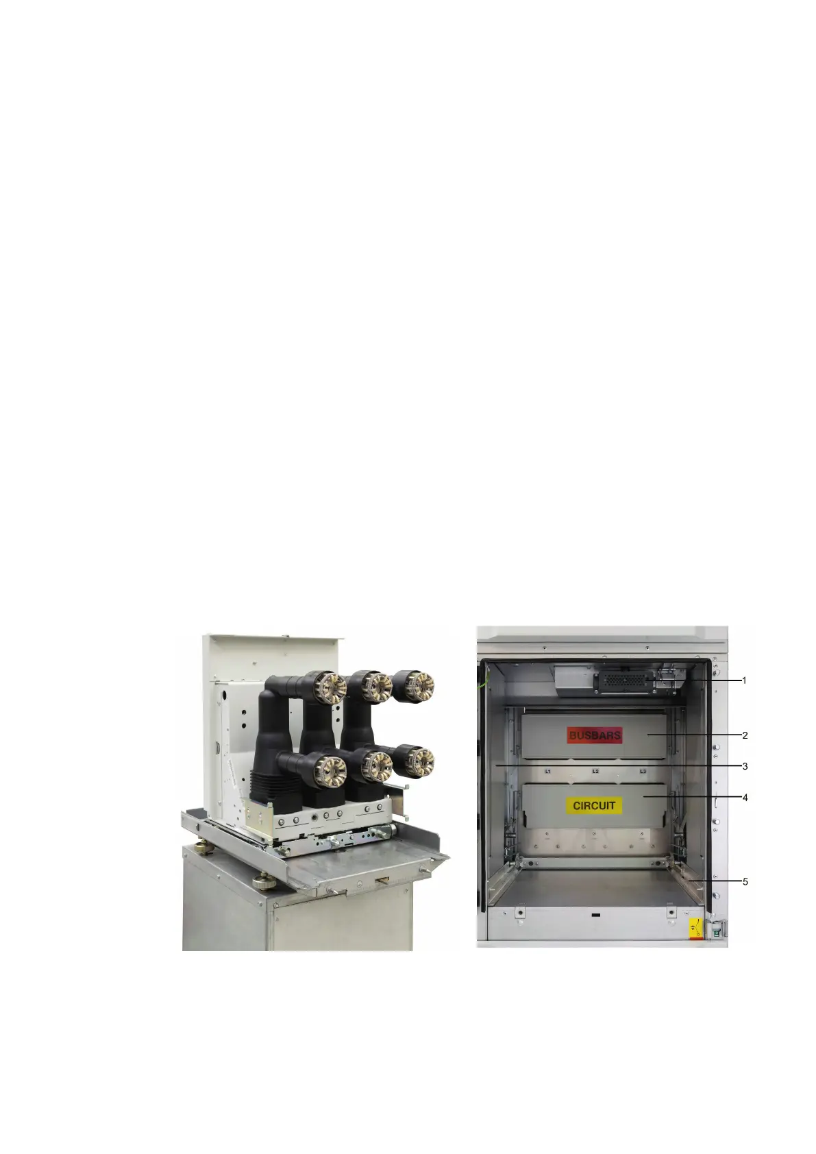
Figure 8: Withdrawable part with VD4 type circuit-
breaker, pole side
Figure 9: View into the circuit-breaker compartment
1 Control wiring socket
2 Top shutter
3 Duct cover
4 Lower shutter
5 Right-hand travel rail

 Loading...


