19
—
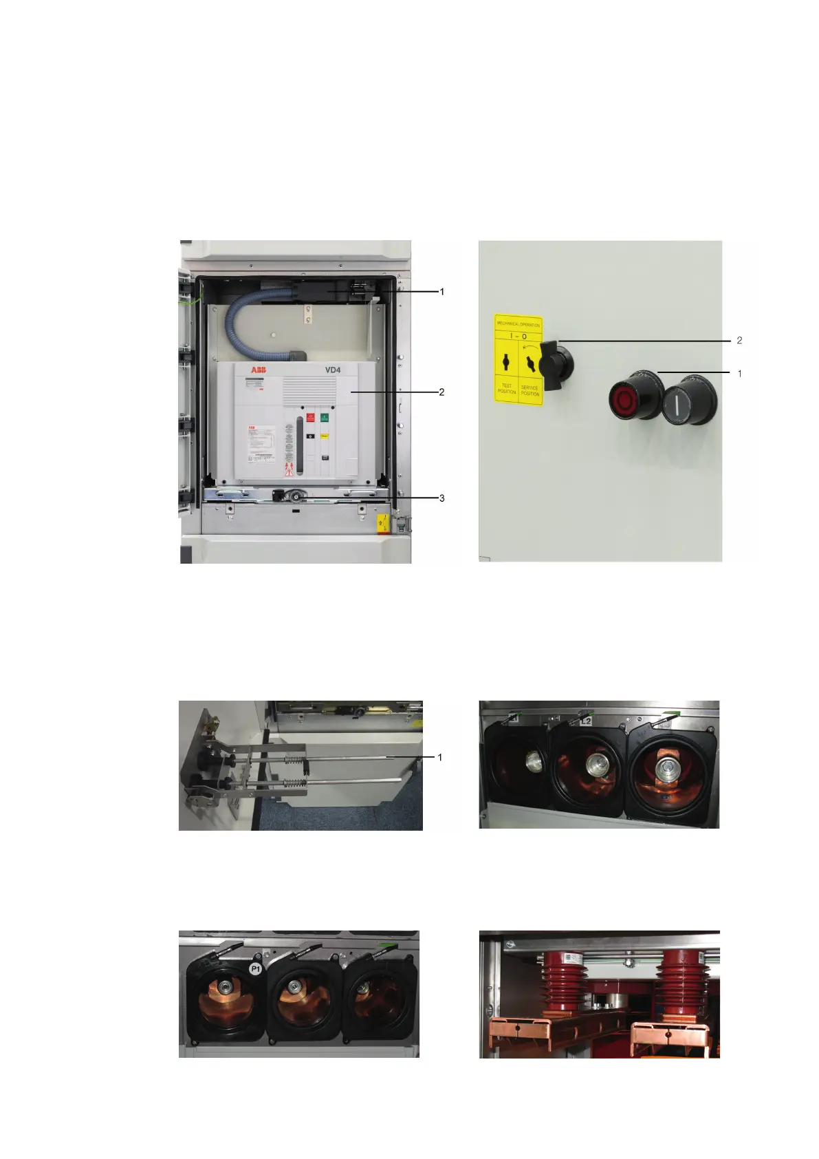
4. Panel design and equipment
Figure 10: Circuit-breaker compartment, open Figure 11: Push button for mechanical ON/OFF breaker
operation with the door closed (on request)
Figure 12: View of the push rod extension swung out by
the knob at the front, with the withdrawable circuit-
breaker part in service position and the door open
Withdrawable part in test position, control wiring
plug connector open
1 Control wiring plug
2 Withdrawable part
3 Square spigot
If the withdrawable part is in the service position,
operation is carried out using the knob which
swings a push rod extension out.
1 Mechanical pushbutton
2 Turning knob
1 Swivelling push rod
Figure 13: Current sensors KECA 80C165 mounted in the
circuit breaker compartment in UniGear ZS1 Digital
Figure 14: Current sensors KECA 80C104 mounted in the
circuit breaker compartment in UniGear ZS1 Digital
Figure 15: Voltage sensors KEVA 17.5B20 mounted in the
cable compartment in UniGear ZS1 Digital

 Loading...


