2106001MNAA | XSERIES G5 START UP GUIDE | 23
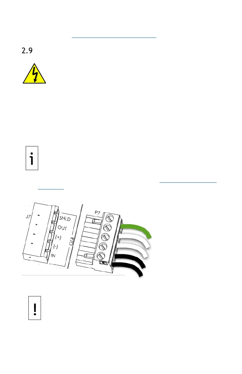
5. Wire the RTD sensor cable to the J7 terminal block using the wires
identified in Figure 2-5: RTD probe connector
, RTD probe connector,
and the pinouts identified in the following.
Wire the RTD to the XFC
WARNING: Bodily injury. Wire
peripheral devices to the flow
computer electronic board before power is applied. If the
flow computer has been powered-up, disconnect power
before performing field wiring.
Wire the RTD:
1. Open the flow computer enclosure door.
2. Using a small slotted screwdriver, remove the RTD terminal
connector from the J7 terminal block.
3. On the RTD probe wire, remove the spade lugs if installed, and trim
the wire cover ends back ¼ inch (6.35 mm).
4. Loosen the screws on the terminal connector for pins 1 through 5.
IMPORTANT NOTE: If the shield is not shorted to the probe, insert
the shield wire to pin 1. Do not connect if the shield wire is shorted
to the probe.
5. Insert the corresponding wires as identified in
Figure 2-5: RTD probe
connector in the RTD pins identified below.
Figure 2-6: RTD sensor wiring to XFC electronic board
6. Gently retighten the terminal connector screws.
NOTICE – Equipment damage. Do not over-tighten the terminal
connector screws as this may damage the wires.
7. Reinsert the terminal connector in the J7 terminal block.

 Loading...